Abstract
In the schematic design phase of framed tube structures, component sizing is a vital task that requires expert experience and domain knowledge. Deep learning-based structural design methods enable machines to acquire expert experiences, but domain knowledge (e.g., empirical laws summarized by engineers from engineering practices) has not been embedded into such data-driven methods, resulting in common sense-conflicting designs. A knowledge-enhanced generative adversarial network is proposed by incorporating a novel differentiable evaluator for compliance checking of domain knowledge. A comparative study indicates that the proposed knowledge-enhanced method is 51% superior to the conventional data-driven method and 150 times faster than a competent engineer. The proposed method facilitates the schematic design of framed tube structures to be automatic and efficient, hence improving the productivity of structural engineers. This study might inspire the development of other knowledge-enhanced deep learning methods and their application in civil engineering.
Keyword
Generative adversarial network; domain knowledge; expert experience; intelligent structural design; framed tube structure
1. Introduction
With rapid urbanization worldwide, framed tube structures have increasingly popular applications in high-rise buildings. The design process of framed tube structures can be generally divided into three phases, namely the schematic design phase, detailed design phase, and construction drawing design phase. As indicated in Figure 1, the impact of decisions is quite significant during the schematic design phase because the subsequent designs are all reliant on the schematic design (Wang et al., 2002). However, the tools in that phase are scarce, because the imprecise and incomplete understanding of design requirements and constraints makes it challenging to use computer-based tools in this early phase (Hsu & Liu, 2000). Therefore, this study focuses on the schematic design phase where the greatest opportunity exists.
Owing to the complexity of the structural system and lack of tools, the schematic design of framed tube structures is a difficult task that relies on expert experience and domain knowledge. Traditionally, senior engineers with adequate design experience and knowledge are responsible for manually developing schematic designs based on the layout, height, seismic risks, and wind loads, laying a foundation for subsequent design phases. The section sizes of structural components, particularly vertical components, are crucial to the schematic design. If the schematic design significantly deviates from the detailed one, the computational, labor, and time costs associated with structural optimization and adjustment will significantly increase. Ideal component section designs could be impractical in some of these circumstances. Currently, the schematic design of the component section size relies exclusively on engineers�� personal experience and knowledge. It is challenging to improve working efficiency beyond human limits and pass on these experiences and knowledge to junior engineers. Therefore, an intelligent design method for component section size is desired in the schematic design phase (Figure 1), which should be capable of accumulating expert experience and mastering domain knowledge, allowing this design phase to be automatic and efficient.
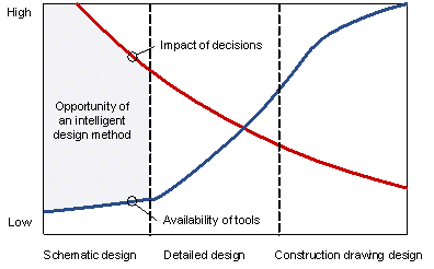
Figure 1 Design process of framed tube structures (modified from Wang et al. (2002))
In recent years, the emerging deep learning has been providing new solutions to structural design, particularly schematic designs that rely on human experience (M��laga-Chuquitaype, 2022). In terms of the schematic design of building structures, deep learning-related methods are mainly based on computer vision techniques that represent structural designs as images (Ampanavos et al., 2021; Liao et al., 2021 & 2022; Pizarro et al., 2021; Lu et al., 2022). Structural design methods based on generative adversarial networks (GANs) have made significant breakthroughs. A GAN is an advanced deep learning framework that comprises two neural networks known as a generator and a discriminator (Goodfellow et al., 2014). GANs can learn complex real-world probability distributions in a game between the generator and discriminator. After reaching Nash equilibrium, GAN can generate realistic image outputs by sampling from learned probability distributions (Newton, 2019; Qian et al., 2021; Rahbar et al., 2022). Specifically, Pizarro et al. (2021) proposed a conceptual design method for shear wall structures, combining a regression model and GAN, Liao et al. (2021 & 2022) and Lu et al. (2022) proposed GAN-based structural wall layout methods, Zhao et al. (2022) proposed a GAN-based design method for beams and slabs, and Fei et al. (2022) proposed a GAN-based shear wall structure design system. Some researchers have also proposed structural design methods based on other deep learning techniques. For example, Chang & Cheng (2020) proposed a structural optimization method based on graph neural networks, the scope of which was limited to frame structures. These studies trained deep learning models on large-scale datasets of existing structural designs, successfully accumulating expert experience to a certain extent and providing powerful tools for schematic design. However, existing methods rarely consider domain knowledge, which is crucial for both structural design and deep learning. The absence of domain knowledge results in problems, including conflicts between generated designs and the common sense of engineers and difficulty in further improving the model performance.
Domain knowledge in structural design is the empirical laws summarized by engineers from engineering practices. Also known as the structural concept, it is a comprehensive reflection on aesthetics, mechanics, constructability, cost, etc. (Lin, 1988). For example, when designing the layout of shear walls, engineers should generally follow the principles of ��symmetry�� and ��periphery�� (Lou et al., 2021), avoid using short-leg walls (Men et al., 2014), consider the location of elevators (Zhou et al., 2022), etc. Domain knowledge can improve the rationality of structural designs in many aspects, making itself an essential factor to be considered in the design process. The embedding of domain knowledge into structural design has been well studied in structural optimization methods using gradient-free algorithms (e.g., genetic algorithm, harmony search, and tabu search) (Chau & Albermani, 2003; Boscardin et al., 2019; Tafraout et al., 2019; Lou et al., 2021). However, these knowledge embedding methods cannot be applied to deep learning models whose optimization relies on gradient-based algorithms (e.g., stochastic gradient descent and Adam).
Existing studies have shown that embedding domain knowledge into deep learning can help improve model performance, reduce data requirements, and accelerate training convergence (Diligenti et al., 2017; Muralidhar et al., 2018). Generally, domain knowledge can be embedded in three stages of deep learning: 1) data collection and preprocessing (Chen & Zhang, 2020), 2) modeling (Ding et al., 2018; Chen et al., 2020; Li et al., 2021); and 3) result interpretation (Dai et al., 2019; Wang & Wu, 2020; Lu et al., 2022). Existing studies show that for the schematic design of building structures, domain knowledge can be embedded in the result interpretation stage (Lu et al., 2022). The key of domain knowledge embedment in this stage is to formulate a quantitative and differentiable evaluation of the model output according to domain knowledge. Only in this manner can the model parameters be optimized by gradient-based algorithms under the guidance of domain knowledge. However, it is difficult to explicitly express domain knowledge in structural design as a machine-readable language in a deep learning framework. Directly applying existing methods may result in gradient interruption. This study attempts to embed domain knowledge of structural design into GANs. This is the first attempt to simultaneously consider the expert experience and domain knowledge in an intelligent structural design to the best of our knowledge.
The main contribution of this study is the proposal of StructGAN-KNWL: a knowledge-enhanced GAN for the schematic design of the component section size of framed tube structures. As a pioneer study, it focuses on the vertical components, which are more critical to the structural system compared to horizontal components. The proposed method can simultaneously consider the expert experience and domain knowledge in structural design, significantly improving design efficiency. Section 2 presents an intelligent design method for the component section size, including the training and application of StructGAN-KNWL. To facilitate the GAN in accumulating expert experience, Section 3 proposes a feature representation and fusion method for design drawings and design conditions. To enable the GAN to master domain knowledge, Section 4 proposes a series of domain knowledge that is important in the component section design of framed tube structures and formulates corresponding differentiable domain knowledge evaluators. Section 5 describes the experiments conducted on the proposed methods and discusses the key hyperparameters of the GAN. Section 6 presents a case study on typical structures and compares the designs of StructGAN-KNWL and those of engineers in terms of mechanical performance, material consumption, design efficiency, and human expert intuition. Finally, Section 7 presents the conclusions of this study.
2. Intelligent design method for component section size
Focusing on the schematic design phase, this paper describes an intelligent design method for the component section size of framed tube structures. Inspired by the working style of human engineers, the proposed method is specially designed to consider both expert experience and domain knowledge. Specifically, the proposed intelligent design method, whose core is StructGAN-KNWL (a knowledge-enhanced GAN), can be divided into the training and application stages, as shown in Figure 2.
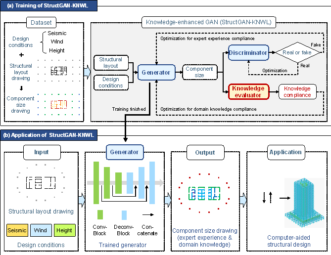
Figure 2 Intelligent design method for component section size
a) Training stage: First, a dataset is established by collecting the design drawings and design conditions of framed tube structures. Next, StructGAN-KNWL is trained and tested on the dataset, learning both expert experience and domain knowledge, as shown in Figure 2(a).
b) Application stage: First, the structural layout drawing and design conditions of the target building are input into the generator of the pre-trained StructGAN-KNWL to obtain the component size drawing. Then, the component size drawing is used in the computer-aided structural design software (e.g., PKPM and ETABS) for subsequent detailed designs, as shown in Figure 2(b).
Details are introduced in the subsequent subsections: knowledge-enhanced GAN in Subsection 2.1, training strategy of the knowledge-enhanced GAN in Subsection 2.2, dataset establishment in Subsection 2.3, and preprocessor and postprocessor of the GAN in Subsection 2.4.
2.1 Knowledge-enhanced GAN
Traditional GANs are data-driven models that consider only expert experience by learning from existing data (i.e., structural designs by engineers in this study). To further embed domain knowledge into GANs, the knowledge-enhanced GAN (StructGAN-KNWL) is proposed, as illustrated in Figure 3.
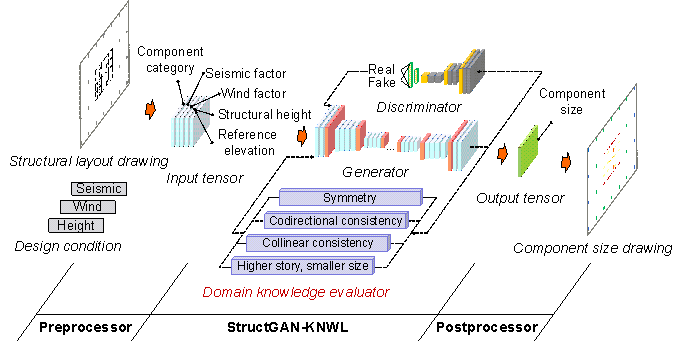
Figure 3 Preprocessor, StructGAN-KNWL, and postprocessor
Based on literature review and consultation with experienced engineers, the following domain knowledge is discussed in this study, focusing on the component section design:
1) Symmetrically positioned components should share the same section size owing to aesthetics and mechanics requirements (Stromberg et al., 2011; Song et al., 2016; Lou et al., 2021);
2) Component sections should be grouped because of constructability and cost requirements (Fischer & Tatum, 1997; Kripka et al., 2015; Boscardin et al., 2019; Chang & Cheng, 2020);
3) For the vertical components of regular structures, the section size on a higher story should be smaller than or equal to that on a lower story owing to mechanics requirements (Boscardin et al., 2019; Sarcheshmehpour et al., 2020).
Details are described in Section 4. Note that the above-mentioned domain knowledge is used as typical example in this study. Other domain knowledge can also be embedded in StructGAN-KNWL using the proposed methods.
The core of the proposed StructGAN-KNWL is a domain knowledge evaluator, which provides a quantitative and differentiable evaluation of component section size based on domain knowledge (see Subsection 4.2 for details).
Based on the domain knowledge evaluator, the loss function of the GAN��s generator is modified, as shown in Equations (1)-(3):
|
|
(1) |
|
|
|
(2) |
|
|
|
(3) |
where ![]() is the loss function of the generator;
is the loss function of the generator; ![]() is the loss function focusing on expert experience, which
follows the data-driven model pix2pix (Isola
et al., 2017) and has been proven suitable for structural design
tasks (Liao et al., 2021 &
2022; Pizarro et al., 2021);
is the loss function focusing on expert experience, which
follows the data-driven model pix2pix (Isola
et al., 2017) and has been proven suitable for structural design
tasks (Liao et al., 2021 &
2022; Pizarro et al., 2021);
![]() is the loss function focusing on domain knowledge, which
is proposed in this study.
is the loss function focusing on domain knowledge, which
is proposed in this study.
![]() is a linear combination of
is a linear combination of ![]() and
and ![]() .
. ![]() reflects the ability of the generator to ��fool�� the discriminator
by generating real-looking designs.
reflects the ability of the generator to ��fool�� the discriminator
by generating real-looking designs. ![]() reflects the similarity between the generated design and
the engineer��s design by computing the one-norm of the difference between
the output and label tensors.
reflects the similarity between the generated design and
the engineer��s design by computing the one-norm of the difference between
the output and label tensors. ![]() adjusts the weights of the above-mentioned loss functions.
adjusts the weights of the above-mentioned loss functions.
![]() comprises several domain knowledge loss functions.
comprises several domain knowledge loss functions. ![]() is the i-th domain knowledge loss function, which
depends on the embedded domain knowledge (see Section 4).
is the i-th domain knowledge loss function, which
depends on the embedded domain knowledge (see Section 4). ![]() is the weight of the i-th domain knowledge function.
is the weight of the i-th domain knowledge function.
![]() and
and ![]() are used to adjust the weights of the expert experience
and domain knowledge loss functions in the training stage.
are used to adjust the weights of the expert experience
and domain knowledge loss functions in the training stage.
2.2 Training strategy of knowledge-enhanced GAN
A two-stage training strategy is further proposed
for StructGAN-KNWL described in Subsection 2.1. The first training stage is
solely data-driven, and ![]() is dominated by
is dominated by
![]() . At this stage, GAN accumulates expert
experience by imitating a large number of real-world project cases and learns
the probability distribution of the designs. The second training stage is
co-driven by data and domain knowledge, and
. At this stage, GAN accumulates expert
experience by imitating a large number of real-world project cases and learns
the probability distribution of the designs. The second training stage is
co-driven by data and domain knowledge, and
![]() is governed by both
is governed by both
![]() and
and
![]() . At this stage, the GAN adjusts the
learned probability distribution under the guidance of domain knowledge such
that its design considers both expert experience and domain knowledge. Furthermore,
the above two-stage training strategy can be implemented by adjusting the
hyperparameters
. At this stage, the GAN adjusts the
learned probability distribution under the guidance of domain knowledge such
that its design considers both expert experience and domain knowledge. Furthermore,
the above two-stage training strategy can be implemented by adjusting the
hyperparameters ![]() and
and
![]() . The recommended values of these hyperparameters
are determined experimentally in Section 5.
. The recommended values of these hyperparameters
are determined experimentally in Section 5.
2.3 Dataset
To enable the GAN to learn useful expert experience, a structural design dataset is established on real-world framed tube structure projects from famous architectural design institutes in China. Design information of 52 framed tube structures is collected, with 276 standard stories. These buildings are distributed across 17 provinces in China and have different seismic and wind design conditions. Their heights range from 56.7 m to 213.7 m, and their widths range from 16.0 m to 63.0 m.
The collected design information includes computer-aided design (CAD) structural drawings in the DWG format and design conditions in the CSV format. Generally, a building comprises multiple standard stories, each of which has its design drawings and conditions. For design drawings, key element extraction is performed to remove unnecessary elements, thereby facilitating the training of deep learning models (Liao et al., 2021). Specifically, unnecessary information, such as axes and annotations, is removed, and only the components to be designed (frame columns and shear walls) are retained. Thus, a structural layout drawing (with only component category attributes) and a component size drawing (with additional section size attributes) can be obtained, as shown in Figure 4(a). The design conditions can be divided into three categories: seismic, wind, and height design conditions. They are further summarized into four design condition features (seismic influential factor, wind influential factor, structural height, and reference elevation), as shown in Table 1. The details of the design condition features are described in Subsection 3.2. Note that the buildings in this study have regular vertical layouts. Consequently, the standard stories of the same building share the same design condition features, except for the reference elevation.
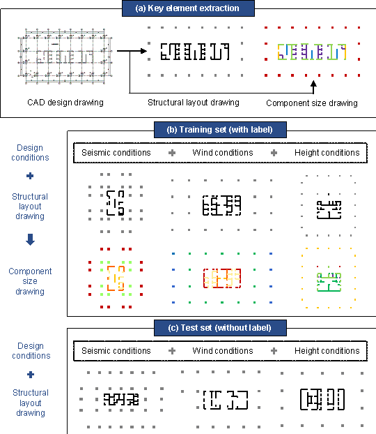
Figure 4 Dataset
Table 1 Design conditions of a standard story
|
Class |
Property |
Feature |
|
Seismic design condition |
Seismic design intensity |
Seismic influential factor |
|
Seismic design acceleration |
||
|
Seismic design group |
||
|
Site class |
||
|
Wind design condition |
Reference wind pressure |
Wind influential factor |
|
Terrain roughness |
||
|
Height design condition |
Structural height |
Structural height |
|
Standard story elevation range |
Reference elevation |
The dataset is divided into a training set and a test set in a ratio of 3:1. The training set consists of 39 buildings (with 205 standard stories) and contains structural layout drawings, design conditions, and corresponding component size drawings, as shown in Figure 4(b). The test set consists of 13 buildings (with 71 standard stories) and contains only structural layout drawings and design conditions, as shown in Figure 4(c). Note that the standard stories of the same building must not be separated into training and test sets. The seismic influential factor, wind influential factor, and structural height have similar distributions on the buildings in the training and test sets (Figure 5), indicating that the test set is representative. Furthermore, the dataset is enlarged by eight times through data augmentation (90�� rotation and mirroring).
|
|
|
|
|
|
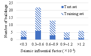
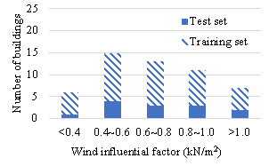
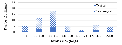
Figure 5 Distribution of design condition features on the dataset (before data augmentation)
2.4 Preprocessor and postprocessor
Similar to other deep-learning models, GAN operates on tensors and cannot be directly used in tasks that require the input of two incompatible data formats (i.e., design drawings in the DWG format and design conditions in the CSV format). In other words, the dataset described in Subsection 2.3 cannot be directly used in the training of GANs. Therefore, a preprocessor and postprocessor are proposed for StructGAN-KNWL. In the training stage, the key features in the structural layout drawings and design conditions are represented as input tensors, and those in the component size drawings are represented as output tensors. The GAN learns a mapping between the input and output tensors. In the application stage, key features in the structural layout drawings and design conditions are also represented as input tensors. After being generated by the GAN, the output tensors are reversely represented as component size drawings for subsequent detailed designs, as shown in Figure 3. The core of the preprocessor and postprocessor is the feature representation and fusion of design drawings and conditions (see Section 3 for details).
3. Design feature representation and fusion
3.1 Design drawing representation
Structural designs are traditionally stored as CAD drawings, whereas GANs can only operate on tensors. Therefore, in both the training and application stages, StructGAN-KNWL must represent the structural layout drawings as input tensors through the preprocessor. The postprocessor needs to represent the component size drawings as output tensors in the training stage and reversely represent the output tensors as component size drawings in the application stage.
The operations of the preprocessor are shown in Figure 6(a):
Step 1: Establish a standardized grid. The total size and unit size of the grid are determined according to the maximum width of the structure and minimum spacing of the structural components, respectively. For the dataset established in Subsection 2.3, the maximum width of the structures is 63.0 m and the minimum spacing of the components is larger than 0.25 m. Therefore, a standardized grid with a total size of 64 m �� 64 m is established, whose unit size is 0.25 m �� 0.25 m. A larger total size and smaller unit size are likely to increase the applicability of the GAN but also result in a higher demand for computational resources. According to relevant engineering practice surveys, the above grid can satisfy the design requirements of most framed tube structures in China. Therefore, the above-mentioned standardized grid is used as an example in this study. It is worth noting that the grid can be easily adjusted to fit any structure while maintaining the feasibility of the proposed method.
Step 2: Position the structural components in the standardized grid. The structural components in the structural layout drawing are mapped to the nearest grid point according to their center positions (geometric center of the frame column and centerline of the shear wall).
Step 3: Represent the standardized grid as the component positioning
matrix ![]() . The grid points where the structural components
exist are represented by 1, and the other grid points are represented by 0.
The matrix size is 256 �� 256 for the standardized grid (64 m �� 64 m total
size and 0.25 m �� 0.25 m unit size) described in Step 1.
. The grid points where the structural components
exist are represented by 1, and the other grid points are represented by 0.
The matrix size is 256 �� 256 for the standardized grid (64 m �� 64 m total
size and 0.25 m �� 0.25 m unit size) described in Step 1.
Step 4: Obtain component category matrix
![]() based on the component positioning
matrix
based on the component positioning
matrix ![]() . To facilitate the embedding of domain
knowledge, the vertical components of the framed tube structures are divided
into m + n + 2 categories, where m and n denote the number
of unparallel directions of the exterior and interior walls of the core tube,
respectively. Specifically, the component categories include 1) the frame
columns, 2) exterior walls of the core tube (m categories for m
unparalleled directions), 3) interior walls of the core tube (n categories
for n unparalleled directions), and 4) other components. For common
core tubes with shear walls positioned along the X and Y directions,
m = n = 2. The above m + n + 2 component categories are represented
by different codes so that each component category can be extracted from the
output tensor of the GAN, facilitating the implementation of domain knowledge
loss functions (see Subsection 4.2 for details).
. To facilitate the embedding of domain
knowledge, the vertical components of the framed tube structures are divided
into m + n + 2 categories, where m and n denote the number
of unparallel directions of the exterior and interior walls of the core tube,
respectively. Specifically, the component categories include 1) the frame
columns, 2) exterior walls of the core tube (m categories for m
unparalleled directions), 3) interior walls of the core tube (n categories
for n unparalleled directions), and 4) other components. For common
core tubes with shear walls positioned along the X and Y directions,
m = n = 2. The above m + n + 2 component categories are represented
by different codes so that each component category can be extracted from the
output tensor of the GAN, facilitating the implementation of domain knowledge
loss functions (see Subsection 4.2 for details).
The operations of the postprocessor are shown in Figure 6(b):
Step 1: Define the mapping relationship. The mapping
between the characteristic size of the structural component and the code in
the component size matrix ![]() is predefined, as in Equation (4):
is predefined, as in Equation (4):
|
|
(4) |
where ![]() is the code in the component size matrix
is the code in the component size matrix ![]() ;
; ![]() is the characteristic size of the structural component
(mm), as shown in Equation (5):
is the characteristic size of the structural component
(mm), as shown in Equation (5):
|
|
(5) |
where ![]() is the thickness of the shear wall and
is the thickness of the shear wall and ![]() is the section area of the frame column. Most of the frame
columns in the framed tube structures have approximately square or circular
sections. Therefore, there is no need to distinguish between the long and
short sides of the columns, thereby reducing the difficulty of deep learning.
Hereafter, the characteristic size of the frame column is referred to as the
equivalent width for easy understanding.
is the section area of the frame column. Most of the frame
columns in the framed tube structures have approximately square or circular
sections. Therefore, there is no need to distinguish between the long and
short sides of the columns, thereby reducing the difficulty of deep learning.
Hereafter, the characteristic size of the frame column is referred to as the
equivalent width for easy understanding.
Step 2: Establish bidirectional mapping based on
component category matrix ![]() . In the training stage, the postprocessor maps
the component size drawing to the component size matrix
. In the training stage, the postprocessor maps
the component size drawing to the component size matrix ![]() , which can be used as the label tensor after normalization.
In the application stage, the postprocessor first de-normalizes the output
tensor into the component size matrix
, which can be used as the label tensor after normalization.
In the application stage, the postprocessor first de-normalizes the output
tensor into the component size matrix ![]() , and then inversely maps the component size matrix
, and then inversely maps the component size matrix
![]() to the component size drawing. The component category matrix
to the component size drawing. The component category matrix
![]() is used in this step to locate and identify the components.
is used in this step to locate and identify the components.
To facilitate the embedding of domain knowledge (see Subsection 4.2 for details), when representing design drawings as matrices, it is necessary to ensure that: 1) the symmetry axis of the structural layout coincides with that of the matrix; 2) collinear shear walls can be in the same row of the matrix after a certain angle of rotation; and 3) vertical components are in the same position in the matrices of all standard stories.
|
(a) Preprocessor |
|
(b) Postprocessor |
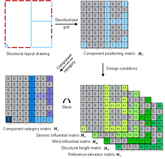
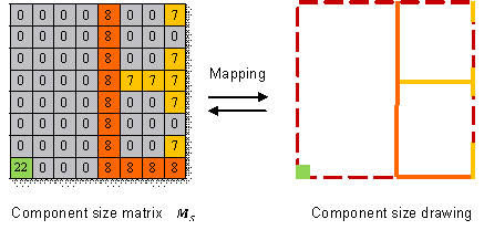
Figure 6 Operations of the preprocessor and the postprocessor
3.2 Design condition representation
Because the component section sizes are affected by the design conditions, the proposed StructGAN-KNWL also involves representation of the design conditions. The dominant design conditions for framed tube structures include seismic, wind, and height design conditions.
For seismic design conditions, the seismic influential factor
![]() is used to reflect the seismic intensity of the structure.
The seismic influential factor
is used to reflect the seismic intensity of the structure.
The seismic influential factor ![]() is related to seismic risk, site conditions, and structural
dynamic characteristics. It can be calculated using Equation (6) (MOHURD, 2010a).
is related to seismic risk, site conditions, and structural
dynamic characteristics. It can be calculated using Equation (6) (MOHURD, 2010a).
|
|
(6) |
where ![]() is the maximum seismic influential factor, which can be
determined according to Table 2;
is the maximum seismic influential factor, which can be
determined according to Table 2; ![]() is the site characteristic period (s), which can be found
in Table 3;
is the site characteristic period (s), which can be found
in Table 3; ![]() is the basic natural period of the structure, which can
be calculated from the empirical formula recommended by the Chinese ��Load
Code for the Design of Building Structures�� (Equation (7)) (MOHURD,
2012).
is the basic natural period of the structure, which can
be calculated from the empirical formula recommended by the Chinese ��Load
Code for the Design of Building Structures�� (Equation (7)) (MOHURD,
2012).
|
|
(7) |
where ![]() and b are the height and width of the structure,
respectively.
and b are the height and width of the structure,
respectively.
Table 2 Maximum seismic influential factor (MOHURD, 2010a)
|
Seismic design intensity |
Seismic design acceleration (10% exceedance in 50 years) |
Maximum seismic influential factor |
|
6 |
0.05 g |
0.12 |
|
7 |
0.10 g |
0.23 |
|
7 |
0.15 g |
0.34 |
|
8 |
0.20 g |
0.45 |
|
8 |
0.30 g |
0.68 |
|
9 |
0.40 g |
0.90 |
Table 3 Site characteristic period (s) (MOHURD, 2010a)
|
Seismic design group |
Site class |
||||
|
|
|
|
|
|
|
|
1 |
0.20 |
0.25 |
0.35 |
0.45 |
0.65 |
|
2 |
0.25 |
0.30 |
0.40 |
0.55 |
0.75 |
|
3 |
0.30 |
0.35 |
0.45 |
0.65 |
0.90 |
For the wind design conditions, the wind influential factor
![]() is used to reflect the wind intensity of the structure.
The wind influential factor
is used to reflect the wind intensity of the structure.
The wind influential factor ![]() is related to the reference wind pressure
is related to the reference wind pressure ![]() and average wind pressure height factor
and average wind pressure height factor ![]() , which can be calculated according to Equations
(8)-(9).
, which can be calculated according to Equations
(8)-(9).
|
|
(8) |
|
|
|
(9) |
where
![]() and
and ![]() are the height difference and wind pressure height factor
of the i-th ground clearance range, respectively, which can be found
in Table A.1 in the Appendix, and n is the number of ground clearance
ranges.
are the height difference and wind pressure height factor
of the i-th ground clearance range, respectively, which can be found
in Table A.1 in the Appendix, and n is the number of ground clearance
ranges.
For the height design conditions, the structural height
![]() and reference elevation
and reference elevation ![]() are considered. The reference elevation
are considered. The reference elevation ![]() can be calculated using Equation (10).
can be calculated using Equation (10).
|
|
(10) |
where ![]() and
and ![]() are the lower and upper elevations of a standard story,
respectively.
are the lower and upper elevations of a standard story,
respectively.
3.3 Fusion of different design features
When designing component section sizes, engineers must comprehensively consider the structural layout and design conditions. Therefore, the proposed StructGAN-KNWL should fuse the input design drawing and design condition features. In this study, a straightforward implementation is adopted. The preprocessor is used to integrate the design drawing features and design condition features into an input tensor, which is then directly fed into the GAN. The experimental results in Section 5 demonstrate that the implementation is effective.
Specifically, the seismic influential matrix
![]() , wind influential matrix
, wind influential matrix ![]() , structural height matrix
, structural height matrix ![]() , and reference elevation matrix
, and reference elevation matrix ![]() are obtained by multiplying the component positioning matrix
are obtained by multiplying the component positioning matrix
![]() by seismic influential factor
by seismic influential factor ![]() , wind influential factor
, wind influential factor ![]() , structural height
, structural height ![]() , and reference elevation
, and reference elevation ![]() , respectively. Thereafter, the component category
matrix
, respectively. Thereafter, the component category
matrix ![]() , seismic influential matrix
, seismic influential matrix ![]() , wind influential matrix
, wind influential matrix ![]() , structural height matrix
, structural height matrix ![]() , and reference elevation matrix
, and reference elevation matrix ![]() are normalized, respectively. Finally, the above matrices
are stacked in the third dimension to obtain the input tensor, as shown in
Figure 6(a). For the 256 �� 256 matrices in Subsection 3.1, the shape of the
input tensor is therefore 256 �� 256 �� 5.
are normalized, respectively. Finally, the above matrices
are stacked in the third dimension to obtain the input tensor, as shown in
Figure 6(a). For the 256 �� 256 matrices in Subsection 3.1, the shape of the
input tensor is therefore 256 �� 256 �� 5.
Additionally, the design feature representation matrices introduced in Section 3 are summarized in Table 4 to clarify the corresponding meanings.
Table 4 Summary of design feature representation matrices
|
Notation |
Name |
Feature representation |
|
|
Component positioning matrix |
Planar position of the components |
|
|
Component category matrix |
Category of the components |
|
|
Seismic influential matrix |
Seismic design condition of the building |
|
|
Wind influential matrix |
Wind design condition of the building |
|
|
Structural height matrix |
Structural height of the building |
|
|
Reference elevation matrix |
Reference elevation of the standard story |
|
|
Component size matrix |
Section size of the components |
Based on the above design feature representation and fusion method, the input tensor-label tensor pairs can be obtained for supervised training of GANs. In this way, the GAN can accumulate expert experience and generate component size designs accordingly.
4. Domain knowledge embedding
4.1 Domain knowledge in component section design
In the schematic design of the component section size, considering only expert experience is insufficient, and appropriate domain knowledge must be embedded. After literature review and consultation with experienced engineers, this study summarizes the domain knowledge required in the schematic design of the component section size (introduced in Subsection 2.1) by considering the following two types of relationships: 1) planar relationship, i.e., the relationship between the section sizes of different components on the same standard story; 2) Vertical relationship, i.e., the relationship between the section sizes of the vertical components on different standard stories. The corresponding loss functions are formulated as follows:
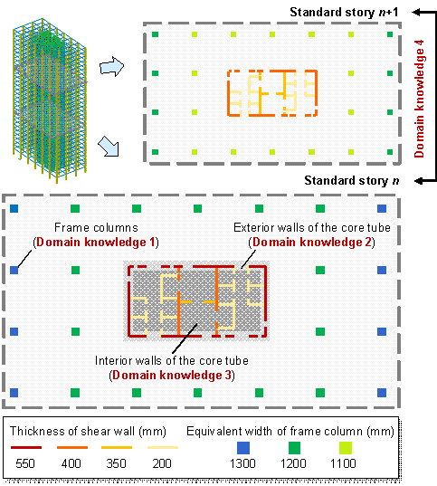
Figure 7 Domain knowledge in the component section design of framed tube structures
1) Planar relationship: for the vertical components of the framed tube structures, the planar relationships include the following specific domain knowledge (Figure 7):
Domain knowledge 1: Symmetrically positioned frame columns should share the same section size owing to aesthetics and mechanics requirements (Stromberg et al., 2011; Song et al., 2016; Lou et al., 2021). On the one hand, symmetry has always been a predominant design element in architecture (Hargittai & Hargittai, 2015). On the other hand, asymmetry of structural components results in a deviation between the center of rigidity and the center of mass, possibly causing undesirable torsion under horizontal actions. The corresponding loss function can be defined using Equation (11):
|
|
(11) |
where
![]() and
and ![]() are the section sizes of a pair of symmetrically positioned
frame columns.
are the section sizes of a pair of symmetrically positioned
frame columns.
Domain knowledge 2: The exterior walls of the core tube, which are positioned along the same direction, should share the same section size because of constructability and cost requirements (Fischer & Tatum, 1997; Kripka et al., 2015; Boscardin et al., 2019; Chang & Cheng, 2020). The uniform thickness of exterior walls can facilitate construction and reduce formwork costs. Note that the exterior walls in different directions might have different section size due to mechanics requirements. The corresponding loss function can be defined according to Equation (12):
|
|
(12) |
where
![]() is the section size of an exterior wall of the core tube,
is the section size of an exterior wall of the core tube,
![]() is the average section size of all the exterior walls positioned
along the same direction as the above-mentioned exterior wall.
is the average section size of all the exterior walls positioned
along the same direction as the above-mentioned exterior wall.
Domain knowledge 3: The interior walls of the core tube, which are positioned on the same straight line, share the same section size because of constructability and cost requirements (Fischer & Tatum, 1997; Kripka et al., 2015; Boscardin et al., 2019; Chang & Cheng, 2020). The uniform thickness of interior walls can also facilitate construction and reduce formwork costs. The corresponding loss function can be defined according to Equation (13):
|
|
(13) |
where
![]() is the section size of an interior wall of the core tube,
is the section size of an interior wall of the core tube,
![]() is the average section size of all the interior walls positioned
on the same straight line as the above-mentioned interior wall.
is the average section size of all the interior walls positioned
on the same straight line as the above-mentioned interior wall.
2) Vertical relationship: for the vertical components of the framed tube structures, the vertical relationships include the following specific domain knowledge (Figure 7):
Domain knowledge 4: For vertical components of regular structures, the section size on a higher standard story should be smaller than or equal to that on a lower standard story owing to mechanics requirements (Boscardin et al., 2019; Sarcheshmehpour et al., 2020). The corresponding loss function can be defined according to Equation (14):
|
|
(14) |
where ![]() and
and ![]() are the component section sizes of the same vertical component
on a higher standard story and a lower standard story, respectively.
are the component section sizes of the same vertical component
on a higher standard story and a lower standard story, respectively.
The above domain knowledge may seem natural to human engineers, but it is quite difficult for GANs to learn. Therefore, this paper describes a differentiable domain knowledge evaluator to solve this problem to a certain extent. It should be noted that the above-mentioned domain knowledge is typical in the structural design and therefore used as examples in this study. Other domain knowledge can also be embedded in StructGAN-KNWL according to specific needs in engineering practice.
4.2 Differentiable domain knowledge evaluator
The key to embedding domain knowledge in deep learning is to realize a differentiable evaluation of the model output based on domain knowledge. To this end, the corresponding differentiable evaluators are proposed for the domain knowledge described in Subsection 4.1.
Based on the input component category matrix ![]() , the positioning masks of different structural
components can be obtained:
, the positioning masks of different structural
components can be obtained: ![]() ,
, ![]() (1 �Q i
�Q m), and
(1 �Q i
�Q m), and ![]() (m + 1 �Q j �Q m
+ n). The locations where the specific components
exist are coded as 1, while others are coded as 0. The output tensor of GANs
is denoted as
(m + 1 �Q j �Q m
+ n). The locations where the specific components
exist are coded as 1, while others are coded as 0. The output tensor of GANs
is denoted as ![]() , and the loss functions corresponding to different
domain knowledge can be defined as Equations (15)-(41). The positioning masks
and output tensors are two-dimensional matrices. For convenience, the directions
of these matrices are defined in Figure 8.
, and the loss functions corresponding to different
domain knowledge can be defined as Equations (15)-(41). The positioning masks
and output tensors are two-dimensional matrices. For convenience, the directions
of these matrices are defined in Figure 8.
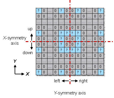
Figure 8 Definition of the directions in the matrix
Domain knowledge 1: The loss function for the symmetry of frame columns can be defined as Equation (15).
|
|
(15) |
where ![]() and
and ![]() are the loss functions of the X- and Y-symmetry
axes, respectively (Figure 8). Consider
are the loss functions of the X- and Y-symmetry
axes, respectively (Figure 8). Consider ![]() as an example, which can be defined by Equations (16)-(21):
as an example, which can be defined by Equations (16)-(21):
|
|
(16) |
|
|
|
(17) |
|
|
|
(18) |
|
|
|
(19) |
|
|
|
(20) |
|
|
|
(21) |
where
![]() and
and ![]() are the left and right halves of
are the left and right halves of ![]() , respectively (Figure 8);
, respectively (Figure 8); ![]() and
and ![]() are the left and right halves of
are the left and right halves of ![]() , respectively (Figure 8);
, respectively (Figure 8); ![]() is a function that returns the sum of all elements in the
input tensor;
is a function that returns the sum of all elements in the
input tensor; ![]() is a function that computes the absolute value of each
element in the input tensor;
is a function that computes the absolute value of each
element in the input tensor; ![]() is the Hadamard (element-wise) multiplication of tensors,
which supports broadcasting;
is the Hadamard (element-wise) multiplication of tensors,
which supports broadcasting; ![]() is a function that flips the input tensor in the left/right
direction.
is a function that flips the input tensor in the left/right
direction.
Domain knowledge 2: The loss function for the codirectional consistency of the exterior walls of the core tube can be defined using Equation (22).
|
|
(22) |
where ![]() is the loss function of the exterior
walls in the i-th direction of all m directions, which can be
defined by Equations (23)-(28):
is the loss function of the exterior
walls in the i-th direction of all m directions, which can be
defined by Equations (23)-(28):
|
|
(23) |
|
|
|
(24) |
|
|
|
(25) |
|
|
|
(26) |
|
|
|
(27) |
|
|
|
(28) |
Domain knowledge 3: The loss function for the colinear consistency of the interior walls of the core tube can be defined by Equation (29).
|
|
(29) |
where
![]() is the loss function of the interior walls in the j-th
direction of all n directions, which can be defined by Equations (30)-(37):
is the loss function of the interior walls in the j-th
direction of all n directions, which can be defined by Equations (30)-(37):
|
|
(30) |
|
|
|
(31) |
|
|
|
(32) |
|
|
|
(33) |
|
|
|
(34) |
|
|
|
(35) |
|
|
|
(36) |
|
|
|
(37) |
where
![]() is a function that rotates the input tensor by an angle
of
is a function that rotates the input tensor by an angle
of ![]() , counter-clockwise;
, counter-clockwise; ![]() is the angle between the j-th direction of the interior
walls and X direction (Figure 8), counter-clockwise;
is the angle between the j-th direction of the interior
walls and X direction (Figure 8), counter-clockwise; ![]() is the element-wise division of tensors;
is the element-wise division of tensors; ![]() is a function that returns the sum of each row of the input
tensor in the X direction (Figure 8);
is a function that returns the sum of each row of the input
tensor in the X direction (Figure 8); ![]() is a small float number, which is used to avoid division
by zero in Equation (35).
is a small float number, which is used to avoid division
by zero in Equation (35).
Domain knowledge 4: The loss function for the decrease of section size with the elevation of the standard story can be defined by Equations (38)-(40).
As a type of vertical relationship, this domain
knowledge considers the relationship between section sizes on different standard
stories. Therefore, three adjacent standard stories of the same building should
be input into the GAN for prediction respectively. The output tensors are
denoted as ![]() ,
, ![]() , and
, and ![]() according to the reference elevation of the input standard
story.
according to the reference elevation of the input standard
story.
|
|
(38) |
|
|
|
(39) |
|
|
|
(40) |
where ![]() is an activation function that applies the rectified linear
unit function to each element of the input tensor, as defined in Equation
(41):
is an activation function that applies the rectified linear
unit function to each element of the input tensor, as defined in Equation
(41):
|
|
(41) |
The adoption of the ![]() function is to ensure that a positive value is added to
function is to ensure that a positive value is added to
![]() when the component section size on a higher story is larger
than that on a lower story (
when the component section size on a higher story is larger
than that on a lower story ( ![]() ) and
) and ![]() is not changed under other circumstances (
is not changed under other circumstances ( ![]() ). So that the StructGAN-KNWL model is guided to avoid the violation
of domain knowledge 4.
). So that the StructGAN-KNWL model is guided to avoid the violation
of domain knowledge 4.
5. Numerical experiments and discussion
The proposed StructGAN-KNWL is implemented in the PyTorch deep learning framework and trained on a computer with a Windows system and an NVIDIA GeForce RTX 3090 GPU. Similar to other deep-learning models, StructGAN-KNWL has some hyperparameters that need to be tuned. After small-scale parameter tuning, the hyperparameters inherited from pix2pix (Isola et al., 2017) are selected, as shown in Table 5. The training time of the StructGAN-KNWL model with these hyperparameters is approximately 5 hours using a GPU and remains basically constant for all the experiments in this section. It should be noted that these parameters may not be optimal. Although large-scale parameter tuning can lead to better hyperparameters, this is not the focus of this study. The remainder of this section focuses on the hyperparameters introduced by the proposed method.
Table 5 Fixed hyperparameters
|
Hyperparameter |
Choice |
|
Number of input channels |
5 |
|
Number of output channels |
1 |
|
Generator architecture (size) |
U-net (256��256) (Ronneberger et al., 2015) |
|
Discriminator architecture (size) |
PatchGAN (70��70) (Isola et al., 2017) |
|
Batch size |
16 |
|
Number of epochs |
600 |
|
Learning rate |
0.0002 |
|
Decay policy |
Linear |
|
Optimizer |
Adam (Kingma & Ba, 2015) |
|
Momentum |
0.5 |
5.1 Results after embedding single domain knowledge
This section discusses a scenario in which only one type of domain knowledge is embedded in the GAN at a time. In this scenario, Equation (3) degenerates into Equation (42).
|
|
(42) |
The two-stage training strategy described in Subsection 2.2
is adopted. The hyperparameters ![]() and
and ![]() as functions of the epoch are shown in Figure 9(a). In
the first stage,
as functions of the epoch are shown in Figure 9(a). In
the first stage, ![]() . In the second stage,
. In the second stage, ![]() increases with epoch and finally
increases with epoch and finally ![]() .
.
|
(a) Scheme 1 |
(b) Scheme 2 |
|
(c) Scheme 3 |
|
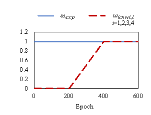
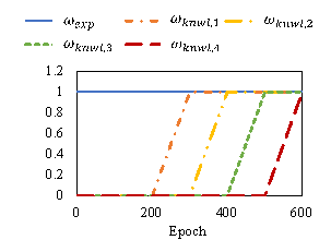
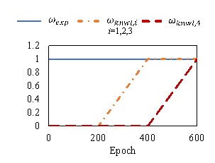
Figure 9 Different schemes of  and
and 
The weights of ![]() ,
, ![]() , and
, and ![]() are adjusted using
are adjusted using ![]() and
and ![]() . According to Isola et al. (2017),
. According to Isola et al. (2017), ![]() . Another hyperparameter
. Another hyperparameter ![]() must be experimentally determined. The relative difference
in the loss function after domain knowledge embedding is defined by Equation
(43):
must be experimentally determined. The relative difference
in the loss function after domain knowledge embedding is defined by Equation
(43):
|
|
(43) |
where ![]() is the loss function of the conventional GAN (without domain
knowledge),
is the loss function of the conventional GAN (without domain
knowledge), ![]() is the loss function of StructGAN-KNWL (with
domain knowledge),
is the loss function of StructGAN-KNWL (with
domain knowledge), ![]() is the relative difference between the above loss functions.
is the relative difference between the above loss functions.
The experimental results for different ![]() values on the test set are presented in Figure 10. This
shows that with an increase in
values on the test set are presented in Figure 10. This
shows that with an increase in ![]() ,
, ![]() gradually decreases, indicating that the designs of StructGAN-KNWL
become better at satisfying the domain knowledge. However,
gradually decreases, indicating that the designs of StructGAN-KNWL
become better at satisfying the domain knowledge. However, ![]() gradually increases at the same time, indicating that the
designs become worse at satisfying the expert experience. Therefore, the weight
of the domain knowledge and expert experience must be balanced by reasonably
selecting the optimal
gradually increases at the same time, indicating that the
designs become worse at satisfying the expert experience. Therefore, the weight
of the domain knowledge and expert experience must be balanced by reasonably
selecting the optimal ![]() (i.e.,
(i.e., ![]() ). It can be observed from Figure 10 that
). It can be observed from Figure 10 that
![]() increases sharply after exceeding 20%, resulting in completely
unreliable designs. To ensure that the designs satisfy expert experience,
it is required that
increases sharply after exceeding 20%, resulting in completely
unreliable designs. To ensure that the designs satisfy expert experience,
it is required that ![]() . The maximum
. The maximum ![]() that satisfies the above requirements is selected as
that satisfies the above requirements is selected as ![]() . The
. The ![]() of different domain knowledge and the corresponding RLoss
are listed in Table 6.
of different domain knowledge and the corresponding RLoss
are listed in Table 6.
|
(a) Domain knowledge 1 |
(b) Domain knowledge 2 |
|
(c) Domain knowledge 3 |
(d) Domain knowledge 4 |
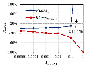
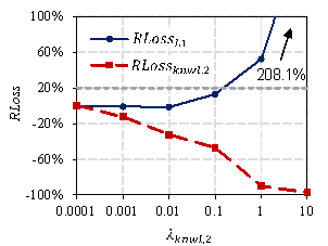
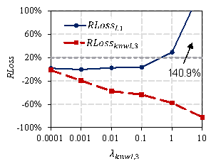
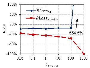
Figure 10 Influence of  on RLoss
Table 6 Optimal  and the corresponding RLoss
|
Domain knowledge No. |
Subject |
|
|
|
|
1 |
Frame columns |
0.1 |
10.9% |
-38.5% |
|
2 |
Exterior walls of the core tube |
0.1 |
12.9% |
-46.9% |
|
3 |
Interior walls of the core tube |
0.1 |
3.4% |
-43.6% |
|
4 |
Vertical components |
100 |
4.8% |
-37.3% |
Table 6 shows that after the embedding of single domain knowledge, the loss functions corresponding to the four types of domain knowledge decrease by 38.5%, 46.9%, 43.6%, and 37.3%, respectively. The rationality of the designs is significantly improved. Typical designs before and after the embedding of domain knowledge are shown in Figure 11. StructGAN-KNWL solves the problems of the asymmetry of frame columns (Figure 11(a)), the inconsistency of the co-directional exterior walls (Figure 11(b)), the inconsistency of the collinear interior walls (Figure 11(c)), and the increase of section sizes with the elevation of the standard story (Figure 11(d)), respectively.
|
(a) Domain knowledge 1 |
|
(b) Domain knowledge 2 |
|
(c) Domain knowledge 3 |
|
(d) Domain knowledge 4 |
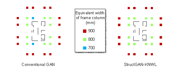
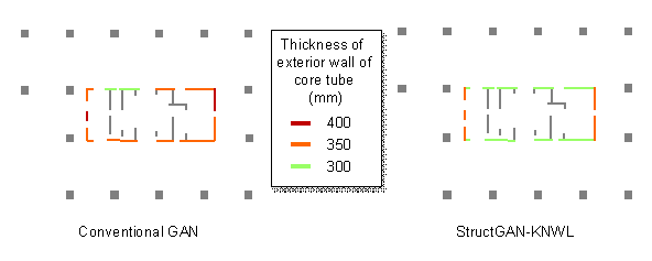
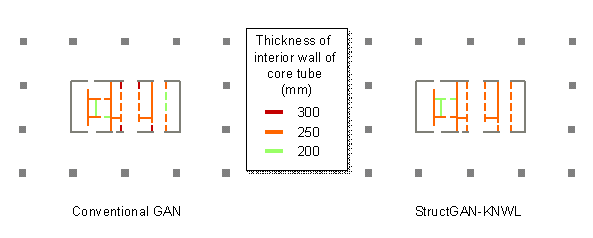
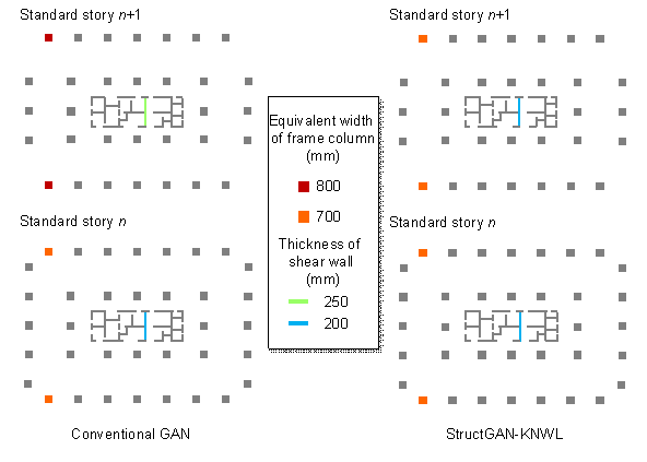
Figure 11 Component section designs generated by GANs with and without domain knowledge
5.2 Results after embedding multiple domain knowledge
This section discusses a scenario in which all four types of domain knowledge are embedded in the GAN. In this scenario, it is difficult to fully optimize the model parameters due to the large amount of embedded domain knowledge. Three schemes for embedding multiple domain knowledge are discussed:
Scheme 1: Embed all types of domain knowledge at the same time, and train only one StructGAN-KNWL model, as shown in Figure 9(a).
Scheme 2: Embed different types of domain knowledge one by one, and train only one StructGAN-KNWL model, as shown in Figure 9(b).
Scheme 3: For frame columns, exterior walls, and interior walls, embed corresponding domain knowledge, respectively, and train three StructGAN-KNWL models. For each category of structural component, both a planar relationship and a vertical relationship are considered, as shown in Figure 9(c). In the application stage, three categories of structural components are respectively generated by the corresponding GAN and then integrated into a complete design.
Based on the ![]() obtained in Subsection 5.1 (Table 6), the experimental
results for different schemes on the test set are presented in Table 7.
obtained in Subsection 5.1 (Table 6), the experimental
results for different schemes on the test set are presented in Table 7.
Table 7 Test set result of multiple domain knowledge embedding
|
Scheme |
|
|
|
|
|
|
1 |
-0.9% |
-26.6% |
-12.6% |
-18.3% |
-37.7% |
|
2 |
-3.1% |
-31.0% |
-15.3% |
9.1% |
-37.2% |
|
3 |
-5.7% |
-38.7% |
-51.2% |
-54.7% |
-59.8% |
It is found that Scheme 3 exhibits the best performance, achieving the best results for all four types of domain knowledge. Domain knowledge losses decrease by 38.7%, 51.2%, 54.7%, and 59.8%, respectively (with an average decrease of 51.1%). In the first training stage, StructGAN-KNWL with Scheme 3 learns the coupled relationship of the frame columns, exterior walls, and interior walls as a whole. In the second training stage, it continues to learn domain knowledge, focusing on a specific type of structural component. The intuitive idea of Scheme 3 is similar to how human engineers work: first, layout the structure as a whole and then adjust the details of certain components.
Furthermore, the domain knowledge losses are lower when two types of domain knowledge are embedded (Table 7) than when only one type of domain knowledge is embedded (Table 6). This is because one of the two types of domain knowledge in Scheme 3 is a planar relationship and the other is a vertical relationship. Therefore, they can complement one another. This indicates that an appropriate combination of domain knowledge is beneficial for joint optimization.
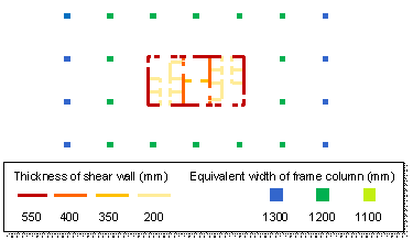
Figure 12 compares the designs of StructGAN-KNWL with Scheme 3 and the designs of engineers, including rectangular, square, and elliptical structural layouts. It can be seen that the designs of StructGAN-KNWL are quite close to those of engineers, successfully satisfying the domain knowledge.
|
(a) Rectangular structural layout |
|
(b) Square structural layout |
|
(c) Elliptical structural layout |
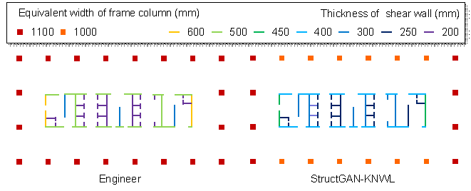
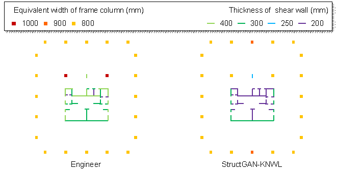
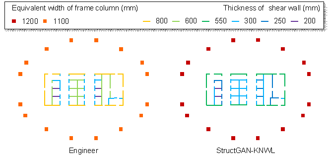
Figure 12 Comparisons between engineer��s design and StructGAN-KNWL��s design
5.3 Discussion on the difference with structural optimization
Meanwhile, the performance of the aforementioned structural optimization methods is solely dependent on the artificially defined design rules reflected in the settings of objective functions, constraints, optimization algorithms, etc. (Aldwaik & Adeli, 2014). However, StructGAN-KNWL is co-driven by data and domain knowledge, and it can automatically learn design rules from data and supplement them with embedded knowledge. For example, StructGAN-KNWL is capable of learning all implicit design objectives, whereas structural optimization only considers those specified in the objective function (i.e., the cost, in most circumstances). As a result, these two approaches are fundamentally different.
In addition, structural optimization methods are computationally intensive. The time required for structural optimization is typically several to dozens of hours (Zhou et al., 2022; Lou et al., 2021; Hasançebi et al., 2011), but StructGAN-KNWL requires only seconds (see Section 6 for details). StructGAN-KNWL has a significant advantage in design efficiency, which is highly crucial during the schematic design phase.
Consequently, in terms of scope, mechanism, and efficiency, StructGAN-KNWL differs significantly from and is rarely comparable to commonly used structural optimization methods.
6. Case study
6.1 Typical case evaluated by structural analysis
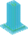
The structural analysis model and design conditions of a 25-story office building are obtained from a real-world project, as shown in Table 8. The section sizes of the frame columns and shear walls of the tower (framed tube structure) are redesigned using the proposed intelligent design method. The other parameters remain unchanged.
Table 8 Structural analysis model and design conditions
|
Structural analysis model |
Design condition |
|
|
Property |
Value |
|
|
|
Seismic design intensity |
7 |
|
Seismic design acceleration |
0.10 g |
|
|
Seismic design group |
2 |
|
|
Site class |
|
|
|
Reference wind pressure |
0.35 kN/m2 |
|
|
Terrain roughness |
B |
|
|
Structural height |
109.20 m |
|
Structural analyses are performed using the PKPM software on the original and redesigned models. The analysis results show that the maximum inter-story drift ratios of StructGAN-KNWL��s design under seismic and wind actions are 4.63% and 5.43% larger than those of the engineer��s design, respectively (Figure 13). However, the inter-story drift ratios of both designs are lower than the 1/800 limit required by the Chinese code (MOHURD, 2010b). In terms of concrete consumption, StructGAN-KNWL's design uses 3.18% less on the frame columns, 1.28% less on the shear walls, and 2.06% less on the sum of the above two, compared with the engineer's design (Table 9). In conclusion, StructGAN-KNWL��s design can reduce concrete consumptions while satisfying the code requirements. Moreover, it generally takes more than 30 min for a competent engineer to design the component section sizes, whereas StructGAN-KNWL requires only 12 s. The working efficiency increases by 150 times.
|
|
|||
|
(a) Seismic action (X-direction) |
(b) Seismic action (Y-direction) |
(c) Wind action (X-direction) |
(d) Wind action (Y-direction) |
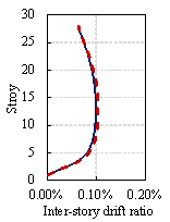
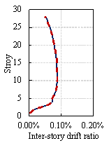
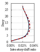
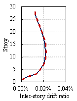
Figure 13 Comparisons between engineers�� design and StructGAN-KNWL��s design on inter-story drift ratios under seismic and wind actions
Table 9 Comparisons between engineers�� design and StructGAN-KNWL��s design on concrete consumption and time cost
|
Designer |
Concrete consumption (m2) |
Time cost |
||
|
Frame column |
Shear wall |
Overall |
||
|
Engineer |
1582.0 |
2291.3 |
3873.3 |
More than 30 min |
|
StructGAN-KNWL |
1531.7 |
2262.0 |
3793.7 |
12 s |
|
Percentage difference |
-3.18% |
-1.28% |
-2.06% |
-99.3% |
6.2 Multiple cases evaluated by human experts
The component section sizes of 40 standard stories are designed by engineers, conventional GANs, and StructGAN-KNWL, respectively. To conduct a professional evaluation of the designs, this study invites engineers, researchers, and graduate students who major in civil engineering and have experience in structural design to complete a questionnaire survey. In the survey, each subject first randomly selects a design from a total of 120 designs, then judges whether it is an ��AI��s design�� or an ��engineer��s design,�� and lastly scores its rationality (1~5, from low to high). This process is repeated eight times for each survey. Typical questions in the questionnaire are listed in Table 10. Note that the designs generated by the GAN-based methods are addressed as ��AI��s design�� for easy understanding.
Table 10 Typical questions in the questionnaire for human experts
|
[Question] Please distinguish the following component size design: AI��s design or engineer��s design? |
|
|
|
l Seismic design intensity: 7 l Seismic design acceleration: 0.15 g l Seismic design group: 1 l
Site class: l Reference wind pressure: 0.90 kN/m2 l Terrain roughness: C l Structural height: 148.70 m l Standard story elevation range: 57.25 m~88.45 m |
|
[Choice] �� AI��s design �� Engineer��s design |
|
|
[Question] Rationality score of the component size design (1 - Irrational, 5 - Rational) |
|
|
[Choice] �� 1 �� 2 �� 3 �� 4 �� 5 |
|
A total of 56 valid questionnaires are obtained. The evaluation results are listed in Table 11. The percentage of designs judged by human experts as ��engineer��s design�� increases by 8.2% to 49.7% for StructGAN-KNWL compared with the conventional GAN (without domain knowledge). In addition, the design rationality score increases by 0.31 to 3.48, which is very close to the engineer��s 3.49. Hence, the proposed StructGAN-KNWL is capable of generating component section designs that seem almost ��real�� to human experts. Because the subjects already know that this survey intends to test whether AI��s design can ��fool�� human experts, they possibly have a psychological tendency to judge the design as ��AI��s design,�� resulting in 30.6% of engineers�� designs being judged as ��AI��s design.��
Table 11 Evaluation results by human experts
|
Designer |
Judged as ��Engineer��s design�� by human experts |
Rationality quantification |
|
Engineer |
69.4% |
3.49 |
|
Conventional GAN |
41.5% |
3.17 |
|
StructGAN-KNWL |
49.7% |
3.48 |
7. Conclusions
This paper describes an intelligent design method for the component section size of framed tube structures, which can automatically generate component section designs in seconds. The core of the proposed method is a knowledge-enhanced GAN (StructGAN-KNWL) that is capable of accumulating expert experience and mastering domain knowledge. To enable the GAN to learn expert experience, design feature representation and fusion methods have been proposed. To embed domain knowledge into the above GAN, four types of domain knowledge are proposed, and the corresponding differentiable evaluators are constructed. The following conclusions can be drawn:
1) A novel knowledge-enhanced GAN (StructGAN-KNWL) is proposed by adding a differentiable domain knowledge evaluator and design feature processors to the pix2pix model. This is the first attempt to simultaneously consider the expert experience and domain knowledge in intelligent structural design.
2) The proposed design feature representation and fusion method can comprehensively consider structural layout drawings and design conditions (including seismic, wind, and height conditions), enabling StructGAN-KNWL to generate designs based on expert experience.
3) The proposed domain knowledge and differentiable evaluators can guide the component section design of framed tube structures. Compared with the conventional GAN, the four domain knowledge losses of StructGAN-KNWL are reduced by 38.7%, 51.2%, 54.7%, and 59.8%, respectively. Moreover, 49.7% of StructGAN-KNWL��s designs are judged as ��engineer��s design�� by human experts, and their rationality scores are close to those of engineers. The working efficiency of StructGAN-KNWL is 150 times higher than that of the engineers.
4) StructGAN-KNWL should be trained using the proposed training strategy. When embedding a single domain knowledge, the optimal domain knowledge weight should be selected experimentally. When embedding multiple domain knowledge, StructGAN-KNWL models should be trained for different structural component categories based on the optimal domain knowledge weights.
Although StructGAN-KNWL has great potential in various knowledge embedding, its knowledge scope is still limited by empirical laws. In the future, the knowledge-enhanced GAN should take into account both physical rules and empirical laws. Furthermore, its applicability in other structure types and design tasks should be investigated further.
Acknowledgment
Competing interests
The authors declare no competing interests.
References
Aldwaik, M., & Adeli, H. (2014). Advances in optimization of highrise building structures. Structural and Multidisciplinary Optimization, 50(6), 899-919. https://doi.org/10.1007/s00158-014-1148-1
Ampanavos, S., Nourbakhsh, M., & Cheng, C.-Y. (2021). Structural design recommendations in the early design phase using machine learning. In Proceedings of the International Conference on Computer-Aided Architectural Design Futures 2021, 190-202. https://doi.org/10.1007/978-981-19-1280-1_12
Boscardin, J. T., Yepes, V., & Kripka, M. (2019). Optimization of reinforced concrete building frames with automated grouping of columns. Automation in Construction, 104, 331-340. https://doi.org/10.1016/j.autcon.2019.04.024
Chang, K.-H., & Cheng, C.-Y. (2020). Learning to simulate and design for structural engineering. In Proceedings of the 37th International Conference on Machine Learning, 1426�C1436. https://doi.org/10.48550/arXiv.2003.09103
Chau, K. W., & Albermani, F. (2003). Knowledge-based system on optimum design of liquid retaining structures with genetic algorithms. Journal of Structural Engineering, 129(10), 1312-1321. https://doi.org/10.1061/(ASCE)0733-9445(2003)129:10(1312)
Chen, S., Leng, Y., & Labi, S. (2020). A deep learning algorithm for simulating autonomous driving considering prior knowledge and temporal information. Computer-Aided Civil and Infrastructure Engineering, 35(4), 305�C321. https://doi.org/10.1111/mice.12495
Chen, Y., & Zhang, D. (2020). Physics-constrained deep learning of geomechanical logs. IEEE Transactions on geoscience and remote sensing, 58(8), 5932-5943. https://doi.org/10.1109/TGRS.2020.2973171
Dai, H., Zhao, G., Lin, M., Wu, J., & Zheng, G. (2019). A novel estimation method for the state of health of lithium-ion battery using prior knowledge-based neural network and Markov chain. IEEE Transactions on Industrial Electronics, 66(10), 7706�C7716. https://doi.org/10.1109/TIE.2018.2880703
Diligenti, M., Roychowdhury, S., & Gori, M. (2017). Integrating prior knowledge into deep learning. In Proceedings of the 16th IEEE International Conference on Machine Learning and Applications (ICMLA), 920�C923. https://doi.org/10.1109/ICMLA.2017.00-37
Ding, X., Luo, Y., Li, Q., Cheng, Y., Cai, G., Munnoch, R., Xue, D., Yu, Q., Zheng, X., & Wang, B. (2018). Prior knowledge-based deep learning method for indoor object recognition and application. Systems Science & Control Engineering, 6(1), 249�C257. https://doi.org/10.1080/21642583.2018.1482477
Fei, Y. F., Liao, W. J., Zhang, S., Yin, P. F., Han, B., Zhao, P. J., Chen, X. Y., & Lu, X. Z. (2022). Integrated schematic design method for shear wall structures: a practical application of generative adversarial networks. Buildings, 12(9), 1295. https://doi.org/10.3390/buildings12091295
Fischer, M., & Tatum, C. B. (1997). Characteristics of design-relevant constructability knowledge. Journal of Construction Engineering and Management, 123(3), 253-260. https://doi.org/10.1061/(ASCE)0733-9364(1997)123:3(253)
Goodfellow, I., Pouget-Abadie, J., Mirza, M., Xu, B., Warde-Farley, D., Ozair, S., Courville, A., & Bengio, Y. (2014). Generative adversarial nets. In Proceedings of the Advances in Neural Information Processing Systems 27. https://doi.org/10.48550/arXiv.1406.2661
Hargittai, I., & Hargittai, M. (2015). The Universality of the Symmetry Concept. In Architecture and Mathematics from Antiquity to the Future (pp. 603-618). Birkhäuser, Cham. https://doi.org/10.1007/978-3-319-00137-1_40
Hasançebi, O., Bahçecioğlu, T., Kurç, Ö. Z. G. Ü. R., & Saka, M. P. (2011). Optimum design of high-rise steel buildings using an evolution strategy integrated parallel algorithm. Computers & Structures, 89(21-22), 2037-2051. https://doi.org/10.1016/j.compstruc.2011.05.019
Hsu, W., & Liu, B. (2000). Conceptual design: issues and challenges. Computer-Aided Design, 32(14), 849-850. https://doi.org/10.1016/S0010-4485(00)00074-9
Isola, P., Zhu, J.-Y., Zhou, T., & Efros, A. A. (2017). Image-to-image translation with conditional adversarial networks. In Proceedings of the IEEE Conference on Computer Vision and Pattern Recognition, 1125�C1134. https://doi.org/10.48550/arXiv.1611.07004
Kingma, D. P., & Ba, J. (2014). Adam: A method for stochastic optimization. In Proceedings of the 3rd International Conference for Learning Representations. https://doi.org/10.48550/arXiv.1412.6980
Kripka, M., Medeiros, G. F., & Lemonge, A. C. (2015). Use of optimization for automatic grouping of beam cross-section dimensions in reinforced concrete building structures. Engineering Structures, 99, 311-318. https://doi.org/10.1016/j.engstruct.2015.05.001
Li, S., Snaiki, R., & Wu, T. (2021). A knowledge-enhanced deep reinforcement learning-based shape optimizer for aerodynamic mitigation of wind-sensitive structures. Computer-Aided Civil and Infrastructure Engineering, 36(6), 733�C746. https://doi.org/10.1111/mice.12655
Liao, W. J., Lu, X. Z., Huang, Y. L., Zheng, Z., & Lin, Y. Q. (2021). Automated structural design of shear wall residential buildings using generative adversarial networks. Automation in Construction, 132, 103931. https://doi.org/10.1016/j.autcon.2021.103931
Liao, W. J., Huang, Y. L., Zheng, Z., & Lu, X. Z. (2022). Intelligent generative structural design method for shear wall building based on ��fused-text-image-to-image�� generative adversarial networks. Expert Systems with Applications, 118530. https://doi.org/10.1016/j.eswa.2022.118530
Lin, T. Y. (1988). Structural Concepts and Systems for Architects and Engineers. Van Nostrand Reinhold. ISBN: 9780442259037.
Lou, H., Gao, B., Jin, F., Wan, Y., & Wang, Y. (2021). Shear wall layout optimization strategy for high-rise buildings based on conceptual design and data-driven tabu search. Computers & Structures, 250, 106546. https://doi.org/10.1016/j.compstruc.2021.106546
Lou, H., Xiao, Z., Wan, Y., Jin, F., Gao, B., & Li, C. (2022). A practical discrete sizing optimization methodology for the design of high-rise concrete buildings. Engineering Computations, 39(6), 2256-2283. https://doi.org/10.1108/EC-08-2021-0473
Lu, X. Z., Liao, W. J., Zhang, Y., & Huang, Y. L. (2022). Intelligent structural design of shear wall residence using physics-enhanced generative adversarial networks. Earthquake Engineering & Structural Dynamics, 51(7), 1657-1676. https://doi.org/10.1002/eqe.3632
M��laga-Chuquitaype, C. (2022). Machine learning in structural design: An opinionated review. Frontiers in Built Environment, 8, 815717. https://doi.org/10.3389/fbuil.2022.815717
Men, J., Shi, Q., & He, Z. (2014). Optimal design of tall residential building with RC shear wall and with rectangular layout. International Journal of High-Rise Buildings, 3(4), 285�C296. https://doi.org/10.21022/IJHRB.2014.3.4.285
MOHURD. (2010a). Code for the Seismic Design of Buildings (GB50011-2010). China Architecture & Building Press. Available at: http://www.jianbiaoku.com/webarbs/book/276/4455702.shtml Last accessed: 7 July 2022. (in Chinese)
MOHURD. (2010b). Technical Specification for Concrete Structures of Tall Building (JGJ 3-2010). China Architecture & Building Press. Available from: http://www.jianbiaoku.com/webarbs/book/228/4499374.shtml Last accessed: 7 July 2022. (in Chinese)
MOHURD. (2012). Load Code for the Design of Building Structures (GB50009-2012). China Architecture & Building Press. Available at: http://www.jianbiaoku.com/webarbs/book/1070/2594462.shtml Last accessed: 7 July 2022. (in Chinese)
Muralidhar, N., Islam, M. R., Marwah, M., Karpatne, A., & Ramakrishnan, N. (2018). Incorporating prior domain knowledge into deep neural networks. In Proceedings of the 2018 IEEE International Conference on Big Data, 36-45. https://doi.org/10.1109/BigData.2018.8621955
Newton, D. (2019). Generative deep learning in architectural design. Technology|Architecture + Design, 3(2), 176�C189. https://doi.org/10.1080/24751448.2019.1640536
Pizarro, P. N., Massone, L. M., Rojas, F. R., & Ruiz, R. O. (2021). Use of convolutional networks in the conceptual structural design of shear wall buildings layout. Engineering Structures, 239, 112311. https://doi.org/10.1016/j.engstruct.2021.112311
Qian, W., Xu, Y., & Li, H. (2021). A self-sparse generative adversarial network for autonomous early-stage design of architectural sketches. Computer-Aided Civil and Infrastructure Engineering, 37(5). https://doi.org/10.1111/mice.12759
Rahbar, M., Mahdavinejad, M., Markazi, A. H., & Bemanian, M. (2022). Architectural layout design through deep learning and agent-based modeling: A hybrid approach. Journal of Building Engineering, 47, 103822. https://doi.org/10.1016/j.jobe.2021.103822
Ronneberger, O., Fischer, P., & Brox, T. (2015). U-net: Convolutional networks for biomedical image segmentation. In Proceedings of the International Conference on Medical Image Computing and Computer-Assisted Intervention, 234-241. https://doi.org/10.1007/978-3-319-24574-4_28
Sarcheshmehpour, M., Estekanchi, H. E., & Moosavian, H. (2020). Optimum seismic design of steel framed�\tube and tube�\in�\tube tall buildings. The Structural Design of Tall and Special Buildings, 29(14), e1782. https://doi.org/10.1002/tal.1782
Song, H., Ghaboussi, J., & Kwon, T. H. (2016). Architectural design of apartment buildings using the implicit redundant representation genetic algorithm. Automation in Construction, 72, 166-173. https://doi.org/10.1016/j.autcon.2016.09.001
Stromberg, L. L., Beghini, A., Baker, W. F., & Paulino, G. H. (2011). Application of layout and topology optimization using pattern gradation for the conceptual design of buildings. Structural and Multidisciplinary Optimization, 43(2), 165-180. https://doi.org/10.1007/s00158-010-0563-1
Tafraout, S., Bourahla, N., Bourahla, Y., & Mebarki, A. (2019). Automatic structural design of RC wall-slab buildings using a genetic algorithm with application in BIM environment. Automation in Construction, 106, 102901. https://doi.org/10.1016/j.autcon.2019.102901
Wang, H., & Wu, T. (2020). Knowledge-enhanced deep learning for wind-induced nonlinear structural dynamic analysis. Journal of Structural Engineering, 146(11), 04020235. https://doi.org/10.1061/(ASCE)ST.1943-541X.0002802
Wang, L., Shen, W., Xie, H., Neelamkavil, J., & Pardasani, A. (2002). Collaborative conceptual design��state of the art and future trends. Computer-Aided Design, 34(13), 981-996. https://doi.org/10.1016/S0010-4485(01)00157-9
Zhao, P. J., Liao, W. J., Xue, H. J., & Lu, X. Z. (2022). Intelligent design method for beam and slab of shear wall structure based on deep learning. Journal of Building Engineering, 57, 104838. https://doi.org/10.1016/j.jobe.2022.104838
Zhou, X., Wang, L., Liu, J., Cheng, G., Chen, D., & Yu, P. (2022). Automated structural design of shear wall structures based on modified genetic algorithm and prior knowledge. Automation in Construction, 139, 104318. https://doi.org/10.1016/j.autcon.2022.104318
Appendix
Table A.1 Wind pressure height factor (MOHURD, 2012)
|
Ground clearance (m) |
Terrain roughness |
|||
|
A |
B |
C |
D |
|
|
5 |
1.09 |
1.00 |
0.65 |
0.51 |
|
10 |
1.28 |
1.00 |
0.65 |
0.51 |
|
15 |
1.42 |
1.13 |
0.65 |
0.51 |
|
20 |
1.52 |
1.23 |
0.74 |
0.51 |
|
30 |
1.67 |
1.39 |
0.88 |
0.51 |
|
40 |
1.79 |
1.52 |
1.00 |
0.60 |
|
50 |
1.89 |
1.62 |
1.10 |
0.69 |
|
60 |
1.97 |
1.71 |
1.20 |
0.77 |
|
70 |
2.05 |
1.79 |
1.28 |
0.84 |
|
80 |
2.12 |
1.87 |
1.36 |
0.91 |
|
90 |
2.18 |
1.93 |
1.43 |
0.98 |
|
100 |
2.23 |
2.00 |
1.50 |
1.04 |
|
150 |
2.46 |
2.25 |
1.79 |
1.33 |
|
200 |
2.64 |
2.46 |
2.03 |
1.58 |
|
250 |
2.78 |
2.63 |
2.24 |
1.81 |