1 Introduction
In recent years, rapid urbanization and the increasing service life of buildings have brought safety and seismic performance to the forefront of engineering concerns. This issue is especially urgent in earthquake-prone regions, where improving the seismic resilience of structures poses significant challenges. In response, many regions have progressively raised their seismic fortification requirements to ensure adequate seismic capacity. Therefore, many aging buildings struggle to meet current structural stiffness standards, necessitating urgent retrofitting. One of the most commonly used retrofit methods is the installation of buckling-restrained braces (BRBs). 1,2 This method not only enhances the stiffness and load-bearing capacity of structures but also provides excellent energy dissipation and damping performance, effectively reducing seismic responses and ensuring compliance with modern codes. 3�C5
Reinforced concrete (RC) frame structures are widely used in residential and industrial buildings. However, many aging RC frame structures worldwide do not comply with the latest seismic design codes, necessitating seismic retrofitting. For certain aging buildings with insufficient lateral stiffness, alterations to the original layout must be minimized while ensuring the feasibility, effectiveness, and cost-efficiency of the retrofit scheme. BRBs offer a practical solution, as they significantly improve the overall seismic performance without altering the original structural layout. 6 However, designing retrofit schemes often requires multiple iterations of calculation and verification, 7�C9 making the process complex and reliant on engineers' experience. While several studies have explored structural optimization methods to enhance the efficiency of BRB retrofit designs, 10�C12 the numerous design variables, constraints, and objectives often limit these methods to simple frameworks and make them time-consuming. Therefore, an intelligent design for seismic retrofitting requires improvements in both quality and efficiency.
Determining the locations, configurations, and sizes of BRBs is essential during the comprehensive design of a BRB retrofit scheme. Subsequent designs must also address the detailing of connections between the BRB and the original structure, although this aspect is typically overlooked during the conceptual design phase. A BRB generally comprises a yielding steel core, an outer restraining sleeve, and an unbonded isolation material between them. 13 The steel core serves as the primary load-bearing component, providing lateral stiffness to the structure, whereas the outer restraining sleeve confines the core and matches its size. In structural calculations, stiffness and load-bearing capacity are generally evaluated based solely on the steel core. 14 Thus, when retrofitting RC frame structures using BRBs, the primary challenge involves determining both the specific locations of BRBs and equivalent cross-sectional sizes of the steel cores. These two factors are interdependent and collectively define the lateral stiffness and mechanical performance of the structure, requiring iterative calculations and adjustments for optimization. Once the preliminary design of the BRB retrofit scheme is completed, the subsequent sizes of sleeves, detailed steel core sizes, and connection methods between the BRBs and the original structure can be finalized using established design methods. Therefore, this study focuses on determining the locations of BRBs and the equivalent cross-sectional sizes of the steel cores during the preliminary design phase (thereafter, BRB sizes refer to the equivalent cross-sectional sizes of the steel cores).
Section 2 reviews several advanced methods for designing BRB retrofit schemes and related structural solutions. The generative artificial intelligence (AI) design method can rapidly generate structural schemes through data learning; however, often struggles to ensure the rationality of the design outcomes. Conversely, optimization methods can produce more reasonable design schemes, though they tend to be time-consuming and inefficient. By combining generative AI with optimization algorithms, it is possible to leverage the strengths of both approaches, addressing the challenges of improving both the efficiency and quality of BRB retrofit design. This study proposes a two-stage intelligent design method for retrofitting RC frame structures with BRBs, aimed at determining the optimal locations and sizes of BRBs in retrofit schemes. In Stage 1, a generative AI algorithm identifies potential BRB locations based on existing architectural features. In Stage 2, an optimization algorithm determines the specific locations and sizes of BRBs, factoring in mechanical performance requirements. This approach achieves a preliminary design that balances both efficiency and quality in BRB retrofit schemes.
Section 2 presents an in-depth review and analysis of the relevant literature. Section 3 introduces the two-stage intelligent design methodology in detail. Sections 4 and 5 elaborate on the intelligent generative approach used in Stage 1 and the intelligent optimization approach in Stage 2, respectively. Section 6 evaluates the effectiveness of the proposed method through case studies, and finally, Section 7 summarizes the research outcomes and suggests directions for future work.
2 Related work
2.1 Generative AI design
Generative AI can efficiently learn design data and generate novel schemes, and it has already been used in preliminary structural design projects. Liao et al. 15 pioneered the use of a generative adversarial network (GAN) based on the pix2pixHD model 16 to achieve pixel-to-pixel conversion, enabling the intelligent generation of shear wall layout schemes by learning from existing design drawings. This approach was later enhanced by incorporating design constraints 17 and physical mechanisms 18 to improve design outcomes. Similarly, for steel frame braced structures, Fu et al. 19,20 applied the GAN method to first generate frame column arrangements and subsequently produce the bracing layout. In response to the limitations of GANs in generating detailed local features, the diffusion model has been introduced into intelligent structural design. Wang et al. 21 and Zhou et al. 22 fine-tuned the stable diffusion model 23 for shear wall design, whereas Gu et al. 24 developed a diffusion model algorithm specifically tailored for structural design, enhancing design effectiveness. Despite these advancements, research methods that employ generative AI for BRB design remain underexplored.
2.2 Optimization design
Currently, the design of BRBs in frame structures primarily relies on optimization methods, with significant research dedicated to direct design approaches. Key optimization variables include the sizes of beams, columns, slabs, and BRBs, 25�C27 whereas common optimization objectives focus on minimizing structural weight, 28 reducing seismic energy, 25,26 and limiting story drift ratios. 27 In addition, certain studies 25,26,28 introduce mechanical constraints, such as plastic bending of beams and columns and axial deformation of BRBs. Various optimization algorithms have been employed, including genetic algorithms, 27 particle swarm optimization, 28 and other metaheuristic algorithms. 26
In retrofit design, the optimization objectives and constraints remain similar to those in direct design; however, the optimization variables are typically confined to BRB parameters. Farhat et al. 10 used the cross-sectional area of the BRB steel core as an optimization variable, whereas Mohammadi et al. 11 included both the cross-sectional area and the thickness of external welded steel plates. Velasco et al. 12 further considered the location, cross-sectional area, length ratio, and area ratio of BRBs as discrete optimization variables.
However, these methods still exhibit certain limitations. In retrofit design, numerous constraints on BRB location selection remain difficult to address with existing optimization approaches. Consequently, most studies focus only on optimizing the component sizes rather than locations. Although some research 12 has explored the optimization of BRB locations, it struggles to fully account for the varying functional requirements of different buildings. In addition, issues such as an excessive number of optimization variables and low efficiency hinder the potential for demands for fully automated intelligent processes. Moreover, current studies primarily investigate the impact of BRBs on single-span structures, lacking parametric modeling and comprehensive mechanical analysis for entire structures. This shortcoming limits their practical applicability for BRB retrofit design in real-world engineering projects.
2.3 Integration of generative AI and optimization
Generative AI, which aims to fit the probabilistic distribution of designs, still faces limitations in design precision, particularly regarding compliance with specific design code requirements in detailed areas. Optimization algorithms primarily focus on satisfying structural mechanical performance requirements and material consumption constraints, often producing near-optimal solutions. However, this process can be time-intensive. To address these challenges, some studies have proposed combining generative AI with optimization methods, which not only enhances design efficiency but also ensures adherence to empirical codes and mechanical performance requirements. 29 In this approach, generative AI is employed to create preliminary design schemes, whereas optimization algorithms refine these schemes to meet design code specifications. For instance, Chang and Cheng 30 integrated graph neural networks with genetic algorithms, using AI-generated results as seed solutions, significantly improving optimization quality and reducing the number of iterations needed to achieve optimal solutions. Similarly, Fei et al. 31 introduced a self-learning approach that combined AI generation, genetic algorithm optimization, and AI re-learning to address challenges associated with small sample data and long-tail distributions in intelligent structural design. Qin et al. 32 developed a shear wall structure generation and optimization system based on large language models, achieving efficient design through a generate-and-optimize process. The integration of generative AI and optimization methods has proven effective in designing frame and shear wall structures. Therefore, this study adopts a similar approach for BRB retrofit schemes to balance efficiency and quality. Unlike previous research, this study decouples architectural requirements from structural demands, integrating the strengths of generative AI methods and optimization algorithms. AI techniques are employed to capture more qualitative architectural design needs, while optimization algorithms are used to meet the more quantitative structural design requirements, resulting in a clearer and more explicit design mechanism.
3 Two-stage retrofit design using generative AI and optimization
In this study, the preliminary design for the BRB retrofit scheme included determining the specific locations and sizes of BRBs. During the actual design process, locations were determined by architectural requirements and structural analysis, taking into account factors such as avoiding functional areas and stairwells while ensuring structural safety. The sizes of BRBs depend more on structural demands, which need to be determined through specific calculations and analyses to comply with structural code requirements.
Architectural requirements are often challenging to quantify, as their information is embedded within architectural drawings. In contrast, structural requirements must be quantitatively defined through modeling and analysis to comply with design standards and ensure the safety of the final design. This study used a two-stage design method to effectively incorporate both architectural and structural information. In Stage 1, an AI generation algorithm interpreted architectural requirements and identified potential BRB locations. In Stage 2, an optimization algorithm, incorporating mechanical analysis and calculations, determined the precise locations and sizes of the BRBs. The specific process is illustrated in Figure 1.
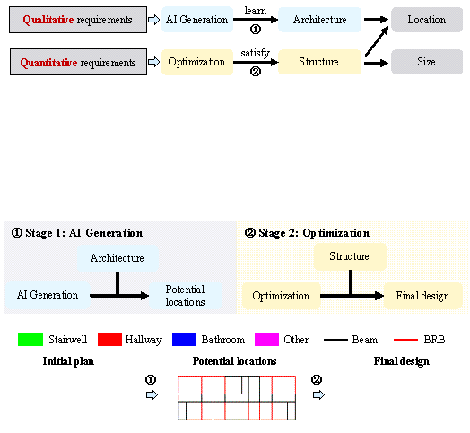
Figure 1. Two-stage intelligent design method for BRB retrofitting of RC frame structures.
In Stage 1, potential BRB locations were identified based on architectural requirements. This task relies heavily on the design experience of engineers and is challenging to accomplish directly through programming or calculations. To address this, a data-driven learning approach can be adopted. By collecting a large dataset of building information paired with corresponding BRB layout data, an AI generation algorithm can learn the underlying distribution patterns within the training data, enabling the automatic generation of potential BRB locations.
In Stage 2, the locations and sizes of BRBs were determined based on structural requirements, necessitating detailed modeling and analysis to ensure structural safety. The specific configuration shapes of BRBs (including the chevron shape and diagonal shape) were established according to the requirements of the angle between the braces and columns stipulated in the ��Code for Seismic Design of Buildings. 33 �� Structural optimization methods were employed to find the optimal solution through iterative calculations and comparisons. Subsequently, additional mechanical calculations 34 were conducted to finalize the locations, configurations, and detailed sizes of the BRB retrofit design.
4 Stage 1: generative AI design based on diffusion models
4.1 Dataset
This study developed a dataset comprising 122 RC frames to facilitate the automatic generation of potential BRB locations in Stage 1. Experienced engineers from design institutes annotated the dataset, identifying potential BRB locations based on the corresponding architectural layout information.
General design guidelines for potential BRB locations included connecting both ends of the BRB to beam-column joints and avoiding placement at room doorways, functional areas, around staircases, or on balconies. In exceptional cases with special design needs, the results from the intelligent generation method in Stage 1 could be manually adjusted to align with particular architectural requirements.
Under normal circumstances, the vertical arrangement of BRBs is generally consistent. Therefore, only one representative standard story was selected from each frame structure, and multi-story conditions were not considered in intelligent generation in Stage 1. The annotated data were stored in DXF format files, with specific features to be annotated listed in Table 1. Each feature was assigned to a separate layer to facilitate subsequent processing.
.
|
Category |
Feature |
Method |
|
Input |
Room type |
Annotated as text within each room |
|
Beam |
Horizontal line segments |
|
|
Column |
Vertical line segments |
|
|
Architectural wall |
Horizontal line segments |
|
|
Output |
Potential BRB location |
Horizontal line segments |
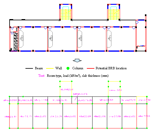
Figure 2. Example of data annotation for generating potential BRB locations in Stage 1.
An example of processing a specific case is illustrated in Figure 2. The dataset was divided into a training set and a test set, with the training set containing 111 drawings and the test set containing 11 drawings.
4.2 Method
Given the diffusion model��s capacity for producing more detailed generative outcomes, 24 this study used the diffusion model to learn data related to potential BRB locations. This method further optimized the representation of data features, enhancing the accuracy of architectural information and controlling the generation process. The specific procedure is illustrated in Figure 3.
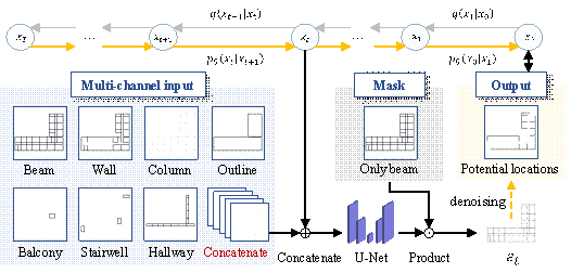
Figure 3. Process of using the diffusion model to learn potential BRB locations.
To ensure that the feature encoding of each component maintains the
same weight and distance relationship, a multi-channel input method
35 was employed. The
features of multi-channel input are determined based on the design experience
of senior engineers. Beams, walls, and columns are fundamental components
of a building, directly influencing the potential BRB locations. The outline
defines the building's boundary, where BRBs are more likely to be installed.
However, areas near balconies, hallways, and stairwells typically do not accommodate
BRBs. Therefore, these features are preliminarily selected as input. Our method represents these elements using separate 0�C1 single-channel
feature matrices, which are then concatenated to construct a multi-channel
feature input for the diffusion model. A U-Net network was used
to predict noise. The Hadamard product of the predicted result ![]() and the mask was computed to narrow the sampling space
for BRB placement, aligning it more closely with actual design requirements.
The final output was obtained through a step-by-step denoising process and
is represented as a 0�C1 single-channel feature matrix, thereby completing
the prediction of potential BRB locations.
and the mask was computed to narrow the sampling space
for BRB placement, aligning it more closely with actual design requirements.
The final output was obtained through a step-by-step denoising process and
is represented as a 0�C1 single-channel feature matrix, thereby completing
the prediction of potential BRB locations.
Gu et al. 24 developed a U-Net model for noise prediction in shear wall structures, providing a mathematical validation of the method��s rationale and experimentally determining the optimal parameters. The model architecture based on this approach is illustrated in Figure 4. This architecture begins by progressively downsampling the image to expand the receptive field and capture low-frequency information. During upsampling, it integrates information from the same hierarchical level through concatenation. Residual blocks were employed to retain information across different hierarchical levels, facilitating the aggregation of multi-level information.
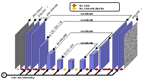
Figure 4. U-Net architecture for noise prediction in potential BRB location generation.
4.3 Results
To evaluate the model's performance, three evaluation metrics were used: precision, recall, and f1_score, defined in Equations (1)�C(3):
![]()
![]()
![]()
where ![]() represents the number of correctly predicted potential
BRB locations,
represents the number of correctly predicted potential
BRB locations, ![]() denotes the total number of predicted potential BRB locations,
and
denotes the total number of predicted potential BRB locations,
and ![]() is the total number of actual potential BRB locations.
Precision evaluates the accuracy of the predicted BRB placements, recall
assesses whether all actual potential BRB locations are identified, and f1_score
provides a balanced measure that considers both precision and recall.
is the total number of actual potential BRB locations.
Precision evaluates the accuracy of the predicted BRB placements, recall
assesses whether all actual potential BRB locations are identified, and f1_score
provides a balanced measure that considers both precision and recall.
The hyperparameters recommended by Gu et al. 24 were selected, and the results are shown in Table 2.
precision
recall
f1_score
Result
0.883
0.917
0.896
As shown in Table 2, the diffusion model method demonstrated a high recall rate, effectively identifying most of the actual potential BRB locations. However, room for improvement remained in precision, as the predicted potential BRB locations were not always accurate. Overall, the f1_score was close to 90%, indicating that the method could generally provide a reasonable and balanced prediction of potential BRB locations.
5 Stage 2: intelligent optimization design
In this section, a parametric modeling and real-time analysis method for retrofit design was developed based on the potential BRB locations obtained in Stage 1. The potential BRB locations and sizes were defined as optimization variables using the online learning algorithm of Y-GAMA. 36 Mechanical performance was formulated as the objective function, enabling rapid optimization of BRB retrofitting and determining the final BRB locations and sizes.
5.1 Optimization variable
The intelligent generation method in Stage 1 reduced the number of optimization variables to a certain extent. However, the number of variables remained relatively high, leading to a significant increase in optimization time. This study introduced the K-Means algorithm for structural design 32 to further enhance optimization efficiency and cluster potential BRB locations, as illustrated in Figure 5.
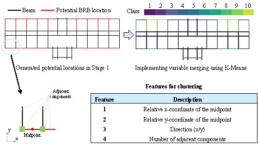
Figure 5. Clustering of potential BRB locations.
The current clustering algorithm temporarily considers 10 categories of potential BRB locations, as recommended by the Y-GAMA online learning algorithm, to balance optimization efficiency and quality. In the example shown in Figure 5, the number of optimization variables was reduced to approximately one-third of the original. In addition, the number of clustering categories can be adjusted according to the structural complexity in specific cases. Clustering features include coordinate information and neighborhood relationships of potential BRB locations, with the possibility of incorporating additional features from supplementary dataset information in the future.
This clustering algorithm offers two key advantages: (1) It significantly reduces the number of optimization variables, ensuring that the number of feasible solutions remains within the range of 103 to 104, thereby greatly enhancing the optimization efficiency, and (2) it effectively leverages the structural layout��s symmetry by applying the same BRB placement to symmetrical positions, resulting in a more rational final design.
Potential BRB locations were defined as optimization variables using the clustering algorithm. In addition, BRB sizes were considered as optimization variables. Since the number of BRBs typically added during structural retrofitting is limited, and construction efficiency must be maximized, it was assumed that all BRBs have the same size, represented by an equivalent rectangular cross-section. The material strength grade was specified as Q235, a commonly used steel in China with a yield strength of 235 MPa. Based on these assumptions, a preliminary design scheme could be developed, allowing for subsequent adjustments in size and material to meet actual design requirements. The ranges and steps of the optimization variables are presented in Table 3.
Table 3. Types, ranges, and steps of optimization variables.
|
Optimization variable |
Quantity |
Range |
Step |
Remarks |
|
Potential BRB location |
10 |
0�C1 |
1 |
0 indicates no BRB |
|
Equivalent length of BRB steel core cross-section |
1 |
60�C120 mm |
20 mm |
Equivalent cross-sectional area of 3600�C14400 mm² |
In practical engineering applications, a BRB material size database can be established based on the selected BRB manufacturer for the project, refining the range of optimization variables to achieve more precise optimization.
According to engineering design experience, 6 the most critical criterion for BRB retrofitting of RC frames with
insufficient lateral stiffness is to satisfy the elastic story drift ratio
requirements under seismic conditions. This is because Chinese design codes
impose strict limits on the elastic story drift ratio for RC frame structures
(1/550). 37 Once this requirement is met, other mechanical performance criteria
are typically satisfied with ease. Consequently, the optimization process
primarily focuses on fulfilling the elastic story drift ratio requirements.
Firstly, the maximum story drift ratio coefficients in the x and y directions,
![]() and
and ![]() , were constructed as shown in Equations (4) and (5).
, were constructed as shown in Equations (4) and (5).
![]()
![]()
where ![]() and
and ![]() represent the maximum story drift ratios in the x and y
directions, respectively,
represent the maximum story drift ratios in the x and y
directions, respectively, ![]() denotes the recommended limit for story drift ratios. This
limit included a certain redundancy based on the ��Code for Seismic Design
of Buildings�� in China 33 and was set at 0.9 times the value of 1/550 for RC frame structures.
38 Parameters 10 and 3 were identified as relatively optimal values through
multiple optimization attempts. Figure 6 illustrates the variation in the
story drift ratio coefficient with respect to the story drift ratio. This
method constructs a continuously differentiable function, where the absolute
value of the derivative is relatively large when the story drift ratio exceeds
the limit, and the curve becomes steeper with greater exceedance. Conversely,
when the story drift ratio is below the limit, the curve remains relatively
smooth with minor variations. This approach enables rapid optimization in
cases of limit exceedance while avoiding excessive optimization.
denotes the recommended limit for story drift ratios. This
limit included a certain redundancy based on the ��Code for Seismic Design
of Buildings�� in China 33 and was set at 0.9 times the value of 1/550 for RC frame structures.
38 Parameters 10 and 3 were identified as relatively optimal values through
multiple optimization attempts. Figure 6 illustrates the variation in the
story drift ratio coefficient with respect to the story drift ratio. This
method constructs a continuously differentiable function, where the absolute
value of the derivative is relatively large when the story drift ratio exceeds
the limit, and the curve becomes steeper with greater exceedance. Conversely,
when the story drift ratio is below the limit, the curve remains relatively
smooth with minor variations. This approach enables rapid optimization in
cases of limit exceedance while avoiding excessive optimization.
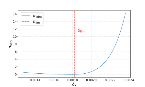
Figure 6. Variation in the story drift ratio coefficient with the story drift ratio (x-direction example).
In addition, the configurations of BRBs should aim to ensure that the stiffness of the structure is comparable in both directions. This can be achieved by controlling the difference in story drift ratios between the two directions and constructing the coefficient of story drift ratio difference, as shown in Equation (6).
![]()
The coefficient of story drift ratio difference is also a continuously differentiable function; however, its weight is slightly lower than that of the story drift ratio. During the optimization process, priority is given to satisfying the story drift ratio limit, followed by the requirement for the story drift ratio difference.
Furthermore,
to control the torsional response of the structure, the distance between the
center of mass and the center of rigidity has to be constrained. The torsional
coefficient ![]() is defined as shown in Equation (7).
is defined as shown in Equation (7).
![]()
where, ![]() is the distance between the center of mass and the center of rigidity,
and
is the distance between the center of mass and the center of rigidity,
and ![]() represents the maximum length of the structure.
represents the maximum length of the structure.
Finally, to maximize the placement of BRBs
on the exterior of the structure, an exterior wall coefficient for BRBs,
![]() , was established, as shown in Equation (8).
, was established, as shown in Equation (8).
![]()
where ![]() represents the number of BRBs placed on the exterior of
the structure, whereas
represents the number of BRBs placed on the exterior of
the structure, whereas ![]() denotes the total number of BRBs to be placed in the structure.
The coefficient 5 is used to reduce the weight of this objective function,
determined through multiple tests and adjustments.
denotes the total number of BRBs to be placed in the structure.
The coefficient 5 is used to reduce the weight of this objective function,
determined through multiple tests and adjustments.
![]()
5.3 Optimization process
The parametric modeling and optimization of the structure were implemented using YJK Y-GAMA.
(1) A reference story was defined, and potential locations for BRBs were determined using the intelligent generation method in Stage 1. This was followed by post-processing based on empirical rules to ensure their rationality. The potential locations and sizes of BRBs in the reference story were established as optimization variables, following the method described in Section 5.1, to achieve parametric modeling.
(2) Floor assembly was conducted, and the vertical assembly of the structure was completed according to floor information. BRBs were arranged on the remaining floors using a vertical alignment method. The horizontal coordinates of the beams in the reference story where the BRBs are located serve as the baseline. If beams identical to those in the reference story exist at the same coordinates in other stories, BRBs are installed; otherwise, they are not.
(3) After completing the floor assembly, design conditions were set, and mechanical calculations were performed. The optimizer module of Y-GAMA was subsequently used to execute the online learning optimization design of BRBs.
The specific graphical programming process is illustrated in Figure 7.

Figure 7. Graphical programming process of the BRB intelligent optimization design in Stage 2 using Y-GAMA.
6 Case study
6.1 Design and analysis of a typical case
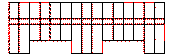
Using an RC frame structure as an example, the implementation process and effectiveness of this method are illustrated. The basic information for the case is as follows: the structure consists of three stories, each with a story height of 3500 mm, and a seismic design intensity of 9 degrees (with a design seismic acceleration value of 0.4 g, corresponding to a 10% probability of exceedance in a 50-year design reference period). The site was classified as Class II, with a seismic grade of 4, design earthquake group 1, fortification category class C, and a characteristic period of 0.35 s. The concrete material used is C30 (standard value of cubic compressive strength of 30 MPa), and the reinforcement is HRB400 (hot-rolled ribbed steel with a yield strength of 400 MPa). The column cross-sectional size is 450 �� 450 mm, while the beam cross-sectional size is 250 �� 700 mm. The original structural layout is presented in Figure 8.
Figure 8. Original structural layout plan.
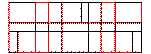
First, the intelligent generation method in Stage 1 was employed using the diffusion model to determine the potential BRB locations, as shown in Figure 9. Areas such as hallways, stairwells, and doorways were excluded from BRB placement to meet architectural requirements.
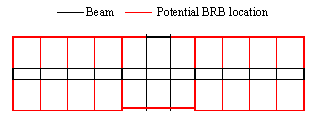
Figure 9. Potential BRB locations.
Subsequently, the intelligent optimization algorithm in Stage 2 was applied for further refinement. Following the recommended values from the YJK software, the total number of computations for online learning was set to 50, with an initial sample size of 10. The optimization process is illustrated in Figure 10.
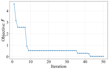
Figure 10. Online learning optimization process.
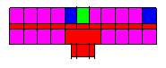
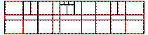
The final locations and sizes of BRBs after optimization are shown in Figure 11. Visually, the BRB placement appears reasonable and maintains symmetry, aligning with structural design principles.

Figure 11. Final locations and sizes of BRBs after optimization.
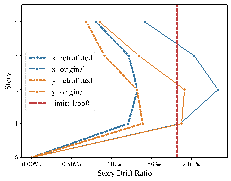
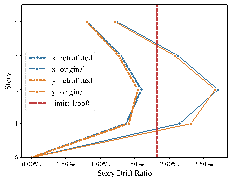
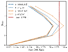
The structure was analyzed in the elastic phase to compare the effects before and after retrofitting, as shown in the story drift ratio comparison in Figure 12. After applying BRB retrofitting, the story drift ratios in both directions met the limit requirements, and the stiffness was approximately uniform, conforming to mechanical performance criteria. In addition, other overall structural and component indicators were checked to ensure compliance with design codes. After initially determining the locations and sizes of BRBs, the configurations and detailed sizes were established based on mechanical calculations. 34 Finally, the Y-JIAN module 39 was employed to perform an elastoplastic analysis, achieving a detailed design that met regulatory and performance requirements and verified the effectiveness of the energy dissipation and damping strategy.
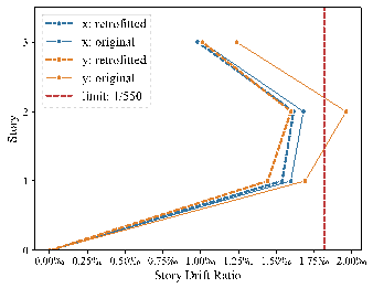
Figure 12. Comparison of story drift ratios before and after retrofitting.
The retrofit design process included the preliminary processing of architectural and structural design drawings, AI generation of potential BRB locations in Stage 1, intelligent optimization of BRB locations and sizes in Stage 2, and final detailed design and verification. The entire process took approximately 40 min. Except for the initial simple preprocessing of drawings (approximately 20 min), the process required minimal manual intervention by engineers, demonstrating that this method could achieve BRB retrofit design automatically and efficiently. In addition, we invited experienced engineers to design the retrofit scheme for this case and conducted experiments using other methods. The comparison results are presented in Table 4.
Table 4. Comparison of results for BRB retrofit scheme design using different methods.
|
Method |
Feasible solution |
Time (min) |
Objective: F |
|
Method A (engineer design) |
�� |
1920 |
�� |
|
Method B (optimization) |
288 |
�� |
�� |
|
Method C (preprocess + AI generation + optimization) |
230 |
410 |
0.180 |
|
Method D (preprocess + K-Means + optimization) |
212 |
40 |
2.680 |
|
Method E (preprocess + AI generation + K-Means + optimization) (i.e., proposed method) |
212 |
40 |
0.030 |
As shown in Table 4, the design method used by engineers (Method A), although relatively reasonable, requires an excessive amount of time. Direct optimization (Method B) results in an overly large feasible solution space (288), making it difficult to obtain optimized results. In addition, the use of AI generation and optimization without K-Means (Method C) led to a large feasible solution space (230), extending the optimization time and limiting effectiveness. Applying only the K-Means algorithm and optimization without AI generation in Stage 1 (Method D) produced suboptimal results that did not account for architectural requirements. In contrast, the proposed method (Method E) effectively balanced optimization efficiency and quality, achieving an improvement in efficiency of nearly 50 times compared to the engineers�� approach, while providing a reasonable BRB retrofit scheme design in a shorter timeframe. Moreover, this method demonstrated good versatility, as it can be applied to the BRB retrofit design of general RC frame structures. The following section presents the design outcomes of several case studies.
6.2 Generalization verification on multiple cases
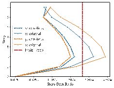
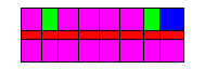
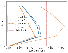
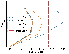
The method was tested on multiple cases to verify its effectiveness, as shown in Figure 13.
![]()
|
The original layout and final BRB placement |
Story drift ratios before and after retrofitting |
|
|
|
|
Equivalent section side length: 60mm |
(a) Case 1 using 41 mins (stories: 7, intensity: 9 (0.4 g), site class: ��, design earthquake group: 1)
|
|
|
|
Equivalent section side length: 60mm |

(b) Case 2 using 36 mins (stories: 4, intensity: 8 (0.3 g), site class: ��, design earthquake group: 1)
|
|
|
|
Equivalent section side length: 60mm |
(c) Case 3 using 34 mins (stories: 4, intensity: 8 (0.3 g), site class: ��, design earthquake group: 1)
|
|
|
|
Equivalent section side length: 60mm |


(d) Case 4 using 42 mins (stories: 4, intensity: 8 (0.2 g), site class: ��, design earthquake group: 2)
|
|
|
|
Equivalent section side length: 80mm |
(e) Case 5 using 19 mins (stories: 4, intensity: 8 (0.3 g), site class: ��, design earthquake group: 3)
|
|
|
|
Equivalent section side length: 80mm |

(f) Case 6 using 37 mins (stories: 3, intensity: 8 (0.3 g), site class: ��, design earthquake group: 1)
Figure 13. Cases of BRB retrofit schemes using the two-stage intelligent design method.
The results indicate that the reinforcement schemes obtained using this method comply with seismic design codes, such as the story drift ratio, and generally meet building requirements, demonstrating good safety and practicality. In addition, the method��s average processing time was around 40 min, further confirming its high optimization efficiency.
7 Conclusion
This study addresses the seismic retrofit problem of RC frame structures by proposing a two-stage intelligent design method based on generative AI and optimization algorithms. Initially, the diffusion model algorithm was employed to determine potential BRB locations according to architectural characteristics, thereby reducing the feasible solution space for optimization. Subsequently, an optimization algorithm was used to specify the locations and sizes of BRBs while considering the mechanical performance requirements of the structure. Case study analyses validated that this method effectively enhanced design efficiency while ensuring the rationality and safety of the reinforcement scheme. The specific conclusions of the study are as follows:
(1) The proposed two-stage intelligent BRB retrofit design method decouples architectural from structural requirements. This method is applicable to various RC frame structures, demonstrating good versatility. It ensures the seismic performance of the structure and complies with design standards through rigorous mechanical performance analysis. Compared to manual methods, it significantly enhances the efficiency of BRB retrofit design and enables a fully automated design process.
(2) The diffusion model is used to learn distribution patterns for potential BRB locations, enabling accurate generation based on architectural characteristics. This reduces reliance on engineers�� experience inherent in traditional design methods, and the effectiveness of this approach has been validated through analysis of various indicators.
(3) The combination of the optimization algorithm with clustering methods significantly reduces the number of optimization variables while constructing a gradient-continuous objective function. This approach enhances optimization efficiency while ensuring the reliability of the final results.
This method enables an effective preliminary design of BRB retrofit schemes. It can also be extended to the retrofit design using conventional braces, although further analysis and verification are required. Notably, the 122 frame structure datasets used for AI training in this method primarily target buildings such as schools and offices. However, other types of buildings, such as shopping malls and hospitals, present more complex requirements for BRB retrofitting due to the diverse functions and extensive application of frame structures. Developing specific training cases for these frame structures is essential to ensure that AI-generated retrofit schemes adequately address the requirements of different functional frame structures.
Acknowledgments
Data Availability Statement
One case from Section 6.1 and six cases from Section 6.2 of the YJK model (YJKS 6.1.0) can be downloaded from the link below, which includes more detailed parameter information of the models:
Appendix A: Training of the diffusion model
The diffusion model excels in generating high-quality and realistic data by iteratively refining predictions through noise reduction, leading to more accurate and stable outputs. Additionally, its probabilistic framework allows for greater flexibility and robustness in handling complex data distributions. The diffusion model described here is based on the framework proposed by Gu et.al. 24 It incorporates a mask tensor, specifically designed to recover masked portions of the target tensor in noisy environments. The following sections provide a detailed explanation of the training and sampling processes.
The goal of the training process is to optimize
the denoising neural network ![]() at the t-th step, which aims to recover the masked parts
of the target tensor
at the t-th step, which aims to recover the masked parts
of the target tensor ![]() from the noisy tensor
from the noisy tensor ![]() . In this process,
. In this process, ![]() represents the multi-channel input condition tensor,
represents the multi-channel input condition tensor, ![]() denotes the mask tensor, and
denotes the mask tensor, and ![]() indicates the noise level, where
indicates the noise level, where
![]() . Here,
. Here, ![]() varies linearly from 0.000001 to 0.01. The procedure is outlined as follows:
varies linearly from 0.000001 to 0.01. The procedure is outlined as follows:
(1) ![]() and
and ![]() are sampled as inputs, representing the information the
model seeks to recover and the conditioning information, respectively.
are sampled as inputs, representing the information the
model seeks to recover and the conditioning information, respectively.
![]() is used to specify the parts of the target tensor that
need to be reconstructed.
is used to specify the parts of the target tensor that
need to be reconstructed.
(2) For a given timestep t, the noise
level ![]() is computed, and noise is injected into the target tensor
to generate the noisy tensor
is computed, and noise is injected into the target tensor
to generate the noisy tensor ![]() as follows:
as follows:
![]()
(3) The noisy tensor ![]() , condition tensor
, condition tensor ![]() , and noise level
, and noise level ![]() are fed into the neural network
are fed into the neural network ![]() , which predicts the noise.
, which predicts the noise.
(4) The loss function is defined as
![]() , where the model optimizes the difference between
the predicted noise and the true noise
, where the model optimizes the difference between
the predicted noise and the true noise ![]() . The gradient of the loss is computed, and the parameters
. The gradient of the loss is computed, and the parameters
![]() of the neural network are updated accordingly, improving
its ability to fit the noise.
of the neural network are updated accordingly, improving
its ability to fit the noise.
The U-Net architecture, as described in Section 4.2, is employed as the neural network model. Training begins with a learning rate of 5 �� 10⁻⁵. Mean Squared Error (MSE) is used to assess the error during both training and validation stages. Validation error is calculated every 100 epochs, and training is terminated if the validation error does not improve for 30 consecutive evaluations. The model with the lowest validation error is selected for predictions and subsequent metric evaluations. The computing platform specifications are as follows: OS: Windows Server 2019 Standard; CPU: Intel(R) Xeon(R) Gold 6226R CPU @ 2.90GHz; RAM: 128 GB; GPU: NVIDIA GeForce RTX 3090 24 GB.
The training process is illustrated in Figure A.1, with a total duration of 42.65 h and a VRAM requirement of approximately 17.2 GB.
Figure A.1. Training process of the diffusion model.
Upon the completion of training, the sampling process starts by generating Gaussian noise and calculating the input tensor at the final time step. The model then iteratively predicts the noise at each step, using this predicted noise to compute the mean and sample the tensor for the previous time step, continuing until the result for the initial time step is produced.
Reference
1. Almeida A, Ferreira R, Proença JM, Gago AS. Seismic retrofit of RC building structures with Buckling Restrained Braces. Engineering Structures. 2017;130:14-22. doi:10.1016/j.engstruct.2016.09.036
2. Zhou Y, Shao HT, Cao YS, Lui EM. Application of buckling-restrained braces to earthquake-resistant design of buildings: A review. Engineering Structures. 2021;246:112991. doi:10.1016/j.engstruct.2021.112991
3. Castaldo P, Tubaldi E, Selvi F, Gioiella L. Seismic performance of an existing RC structure retrofitted with buckling restrained braces. Journal of Building Engineering. 2021;33:101688. doi:10.1016/j.jobe.2020.101688
4. Di Sarno L, Manfredi G. Seismic retrofitting with buckling restrained braces: Application to an existing non-ductile RC framed building. Soil Dynamics and Earthquake Engineering. 2010;30(11):1279-1297. doi:10.1016/j.soildyn.2010.06.001
5. Khampanit A, Leelataviwat S, Kochanin J, Warnitchai P. Energy-based seismic strengthening design of non-ductile reinforced concrete frames using buckling-restrained braces. Engineering Structures. 2014;81:110-122. doi:10.1016/j.engstruct.2014.09.033
6. Cao XY, Shen D, Feng DC, Wang CL, Qu Z, Wu G. Seismic retrofitting of existing frame buildings through externally attached sub-structures: State of the art review and future perspectives. Journal of Building Engineering. 2022;57:104904. doi:10.1016/j.jobe.2022.104904
7. Kim J, Choi H. Behavior and design of structures with buckling-restrained braces. Engineering Structures. 2004;26(6):693-706. doi:10.1016/j.engstruct.2003.09.010
8. Barbagallo F, Bosco M, Marino EM, Rossi PP, Stramondo PR. A multi-performance design method for seismic upgrading of existing RC frames by BRBs. Earthquake Engineering & Structural Dynamics. 2017;46(7):1099-1119. doi:10.1002/eqe.2846
9. Pan Y, An RB, Bai JL, Yan XZ, Jin SS. Seismic design and performance analysis of buckling-restrained braced RC frame structures. The Structural Design of Tall and Special Buildings. 2019;28(15):e1661. doi:10.1002/tal.1661
10. Farhat F, Nakamura S, Takahashi K. Application of genetic algorithm to optimization of buckling restrained braces for seismic upgrading of existing structures. Computers & Structures. 2009;87(1):110-119. doi:10.1016/j.compstruc.2008.08.002
11. Mohammadi RK, Garoosi MR, Hajirasouliha I. Practical method for optimal rehabilitation of steel frame buildings using buckling restrained brace dampers. Soil Dynamics and Earthquake Engineering. 2019;123:242-251. doi:10.1016/j.soildyn.2019.04.025
12. Velasco L, Hospitaler A, Guerrero H. Optimal design of the seismic retrofitting of reinforced concrete framed structures using BRBs. Bull Earthquake Eng. 2022;20(10):5135-5160. doi:10.1007/s10518-022-01394-z
13. Ullah R, Vafaei M, C Alih S, Waheed A. A review of buckling-restrained braced frames for seismic protection of structures. Physics and Chemistry of the Earth, Parts A/B/C. 2022;128:103203. doi:10.1016/j.pce.2022.103203
14. Haider S, Lee D. A review on BRB and SC-BRB members in building structures. Structural Engineering & Mechanics. 2021;80:609-623. doi:10.12989/sem.2021.80.5.609
15. Liao WJ, Lu XZ, Huang YL, Zheng Z, Lin YQ. Automated structural design of shear wall residential buildings using generative adversarial networks. Automation in Construction. 2021;132:103931. doi:10.1016/j.autcon.2021.103931
16. Wang TC, Liu MY, Zhu JY, Tao A, Kautz J, Catanzaro B. High-resolution image synthesis and semantic manipulation with conditional GANs. In: Proceedings of the IEEE Conference on Computer Vision and Pattern Recognition. ; 2018. doi:10.1109/CVPR.2018.00917
17. Liao WJ, Huang YL, Zheng Z, Lu XZ. Intelligent generative structural design method for shear wall building based on ��fused-text-image-to-image�� generative adversarial networks. Expert Systems with Applications. 2022;210:118530. doi:10.1016/j.eswa.2022.118530
18. Lu XZ, Liao WJ, Zhang Y, Huang YL. Intelligent structural design of shear wall residence using physics-enhanced generative adversarial networks. Earthquake Engineering & Structural Dynamics. 2022;51(7):1657-1676. doi:10.1002/eqe.3632
19. Fu BC, Gao YQ, Wang W. Dual generative adversarial networks for automated component layout design of steel frame-brace structures. Automation in Construction. 2023;146:104661. doi:10.1016/j.autcon.2022.104661
20. Fu BC, Wang W, Gao YQ. Physical rule-guided generative adversarial network for automated structural layout design of steel frame-brace structures. Journal of Building Engineering. 2024;86:108943. doi:10.1016/j.jobe.2024.108943
21. Wang LF, Liu JP, Cheng GZ, Liu E, Chen W. Constructing a personalized AI assistant for shear wall layout using Stable Diffusion. Published online May 18, 2023. doi:10.48550/arXiv.2305.10830
22. Zhou Y, Leng H, Meng SQ, Wu H, Zhang Z. StructDiffusion: End-to-end intelligent shear wall structure layout generation and analysis using diffusion model. Engineering Structures. 2024;309:118068. doi:10.1016/j.engstruct.2024.118068
23. Rombach R, Blattmann A, Lorenz D, Esser P, Ommer B. High-resolution image synthesis with latent diffusion models. In: Proceedings of the IEEE/CVF Conference on Computer Vision and Pattern Recognition (CVPR). ; 2022:10684-10695. Accessed September 8, 2024. https://ieeexplore.ieee.org/document/9878449/
24. Gu Y, Huang YL, Liao WJ, Lu XZ. Intelligent design of shear wall layout based on diffusion models. Computer-Aided Civil and Infrastructure Engineering. 2024;n/a(n/a). doi:10.1111/mice.13236
25. Rezazadeh F, Talatahari S. Seismic energy-based design of BRB frames using multi-objective vibrating particles system optimization. Structures. 2020;24:227-239. doi:10.1016/j.istruc.2020.01.006
26. Abedini H, Hoseini Vaez SR, Zarrineghbal A. Optimum design of buckling-restrained braced frames. Structures. 2020;25:99-112. doi:10.1016/j.istruc.2020.03.004
27. Leyva H, Boj��rquez J, Boj��rquez E, Reyes-Salazar A, Carrillo J, L��pez-Almansa F. Multi-objective seismic design of BRBs-reinforced concrete buildings using genetic algorithms. Struct Multidisc Optim. 2021;64(4):2097-2112. doi:10.1007/s00158-021-02965-5
28. Hoseini SM, Parastesh H, Hajirasouliha I, Ferdowsi A. Structural design optimization of all-steel buckling-restrained braces using intelligent optimizers. Int J Steel Struct. 2021;21(6):2055-2070. doi:10.1007/s13296-021-00553-3
29. Liao WJ, Lu XZ, Fei YF, Gu Y, Huang YL. Generative AI design for building structures. Automation in Construction. 2024;157:105187. doi:10.1016/j.autcon.2023.105187
30. Chang KH, Cheng CY. Learning to simulate and design for structural engineering. In: Proceedings of the 37th International Conference on Machine Learning. ; 2020:1426-1436. doi:https://doi.org/10.48550/arXiv.2003.09103
31. Fei YF, Liao WJ, Lu XZ, Taciroglu E, Guan H. Semi-supervised learning method incorporating structural optimization for shear-wall structure design using small and long-tailed datasets. Journal of Building Engineering. 2023;79:107873. doi:10.1016/j.jobe.2023.107873
32. Qin SZ, Guan H, Liao WJ, et al. Intelligent design and optimization system for shear wall structures based on large language models and generative artificial intelligence. Journal of Building Engineering. 2024;95:109996. doi:10.1016/j.jobe.2024.109996
33. GB 50011-2010 Code for seismic design of buildings. Published online 2010. Accessed April 5, 2024. https://www.kscecs.com/standard-2451 (in Chinese)
34. Cheng GY, Ye LP, Cui HC. Study on the design method of buckling-restrained brace. Journal of Building Structures. 2008;29(1):40-48.
35. Han J, Lu XZ, Gu Y, Liao WJ, Cai Q, Xue HJ. Optimized data representation and understanding method for the intelligent design of shear wall structures. Engineering Structures. 2024;315:118500. doi:10.1016/j.engstruct.2024.118500
36. YJK Building Software. Y-GAMA: YJK digital intelligent design software. April 23, 2024. Accessed April 23, 2024. https://www.yjk.cn/article/836/ (in Chinese)
37. Lu XZ, Guan H. Comparison of seismic design and resilience of tall buildings based on Chinese and US design codes. In: Earthquake Disaster Simulation of Civil Infrastructures: From Tall Buildings to Urban Areas. Springer; 2021:171-222. doi:10.1007/978-981-15-9532-5_4
38. Qin SZ, Liao WJ, Lin YQ, Lu XZ. An efficient assessment method for intelligent design results of shear wall structure based on mechanical performance, material consumption, and empirical rules. Engineering Mechanics. 2023;40(12):148-159. doi:10.6052/j.issn.1000-4750.2023.05.0360
39. YJK Building Software. Y-JIAN: YJK seismic mitigation structure design software. 2024. Accessed September 11, 2024. https://www.yjk.cn/article/1403/ (in Chinese)