1 Introduction
Global urbanization has increased demand for the design and construction of high-rise residential buildings comprising shear wall structures [1]. However, traditional design methods rely heavily on engineering judgment, resulting in low efficiency, and requiring substantial computational effort [2]. Therefore, efficient, and intelligent design methods for shear wall structures are required, and automatic shear wall layout generation and optimization methods have developed rapidly in recent years accordingly [2¨C5].
Generative intelligent methods for the design of shear wall structures are primarily based on image representation approaches, such as generative adversarial networks (GANs) [6¨C8] and diffusion models [9,10], or graph representation approaches, such as graph neural networks (GNNs) [11¨C14]. Image representation methods can intuitively display the planar features of the building structure being designed, whereas graph representation methods can intuitively display the topological features of structural component associations, which is more consistent with the natural relationships existing within building structures.
In terms of image representation approaches, Liao et al. [15¨C17] and Lu et al. [18] introduced GAN-based intelligent design methods for shear wall structures that incorporated constraints from architectural images, textual conditions, mechanical indices, and empirical rules to effectively generate structural designs and enhance the efficiency and quality of the resulting shear wall design. Furthermore, Pizarro et al. [3,4] explored shear wall design methods utilizing convolutional neural networks, and Gu et al. [9] and Zhou et al. [10] proposed shear wall layout generation methods using diffusion models to produce high-quality design images.
In terms of graph representation approaches, Zhao et al. [11,12] introduced methods for designing shear walls and beam layouts by leveraging the strong topological feature extraction abilities of GNNs. Zhang et al. [19] developed StrucTopo-GAN, which employed graph representations to generate models comprising nodes and edges for structural design in an end-to-end manner. Similarly, Chang and Cheng [20] modeled building structures as graphs for training a GNN alongside a pre-trained differentiable structural simulator to optimize the cross-sections of columns and beams. These studies collectively demonstrated the potential of GNNs for effectively generating building designs.
Although deep-learning-based intelligent algorithms have achieved notable progress in structural design applications, previously proposed methods for the generative design of shear wall structures have focused solely on obtaining the layout of either shear walls or beams [9¨C11,16,21¨C23]. However, as the separate design of shear walls and beams fails to adequately address the strong interdependence of these components, an intelligent co-design approach for shear wall and beam structures is required. Notably, there exist significant challenges to the realization of such approaches, such as the need to effectively represent coupled design data and develop robust GNN models to address the co-design task, requiring further investigation.
Existing intelligent design methods, such as convolutional neural networks (CNNs) or generative adversarial networks (GANs), primarily focus on image or spatial representations and may not effectively model the topological relationships between different structural elements. Although GANs and CNNs are good at generating structural designs from images or predefined layouts, they have limitations in capturing the interactions between components at the topological and connection levels. In comparison, GNN is essentially designed to handle graphical structural data, where nodes represent structural component nodes (e.g., the disconnection of shear walls and beams), and edges capture relationships (e.g., the length and characteristics of shear walls or beams), making it particularly suitable for this task. By using GNN, this study addresses a key limitation of previous methods: the failure to consider the interdependence of shear walls and beams, thereby achieving more efficient and realistic collaborative design.
Many studies have been conducted to optimize artificial intelligence (AI)-generated structural designs. They have primarily focused on optimizing conventional engineer-designed structures by applying techniques such as genetic algorithms and particle swarm optimization to frame structures [21,24,25], evolutionary algorithms to early-stage architectural spaces [26], and improved genetic algorithms to shear wall designs [5,27]. However, these traditional methods typically fail to address the complex and varied optimization demands of AI-generated designs. Fei et al. [28] addressed this issue by proposing a two-stage evaluation and optimization algorithm to enhance the performance of AI-generated designs, and Qin et al. [29] developed an intelligent optimization system incorporating large language models and generative AI. Similarly, the intelligent co-design of shear wall and beam layouts requires the development of suitable automated optimization techniques to fine-tune the topological aspects and details of AI-generated designs.
The primary objectives of this study are as follows:
Ÿ Develop a unified graph representation method capable of representing shear walls, beams, and non-structural elements simultaneously.
Ÿ Graph Neural Networks (GNNs) that characterize capability walls are used to efficiently co-design shear walls and beams.
Ÿ The shear wall and beam layouts generated by GNN are co-optimized by using rule coding to improve design quality and structural efficiency.
Therefore, this study proposed a method for the intelligent co-design of shear wall and beam layouts in residential buildings that leverages the GNN to address the interdependence of these components. This involved the development of a graph-based co-representation method for walls and beams, a GNN model to generate integrated designs, and an efficient optimization approach. Section 2 elaborates on the overall GNN-based intelligent co-design methodology employed in this study; Section 3 discusses the data fusion and feature engineering applied to integrate the two considered structural components; Section 4 details the GNN model used for training and testing; Section 5 addresses the optimization of the GNN-generated design results using rule-based encoding; and Section 6 describes a case study application and validation of the proposed method using the design of a real-world shear wall structure.
2 A GNN-based co-design method for shear wall and beam layout
2.1 Requirements and methods
Conventional intelligent design methods for shear wall and beam layouts suffer from various limitations, primarily because of their inability to consider the interdependence of these components. The interdependence of shear walls and beams is crucial for improving the efficiency and structural performance of building designs. The position and size of the beams are closely related to the position and strength of the shear walls, as they jointly support and distribute vertical loads, and the beams effectively connect all the shear walls to form a unified whole to resist horizontal loads. Failure to consider this interdependence can lead to inefficient designs that are not optimal in terms of material usage, structural integrity, or spatial efficiency. By integrating the design of both components simultaneously, overall performance can be improved, material costs can be reduced, and the functionality of the building can be enhanced. In the system developed by Qin et al. [30], the shear wall layout was first designed independently based on the input architectural plans, followed by a separate design of the beams according to the shear wall design results. A typical example of this design process is shown in Figure 1 which reflects one of the problems in existing diffusion models. In this case, the AI-generated result exhibits excessively long beams without intermediate support from shear walls, significantly increasing the beam height and reducing the usable space. This design flaw arose because the AI failed to account for the interdependence of the shear wall and beam layouts.
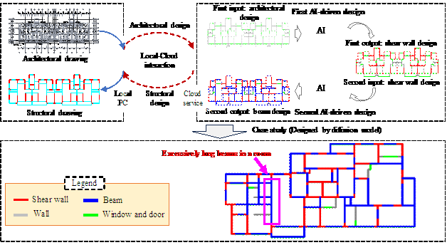
Figure 1 AI-based independent design of shear wall and beam layouts
To address this issue, the AI must simultaneously generate shear wall and beam layouts accounting for their interdependence. This study accordingly proposed a co-design method using a GNN with rule-based encoded optimization, as illustrated in Figure 2. This approach comprises three key steps: first, existing drawing data are cleaned and transformed into graph representations, then these graph data are used to train a GNN, and finally, the GNN-generated designs are optimized through post-processing based on engineering rules and expert knowledge.
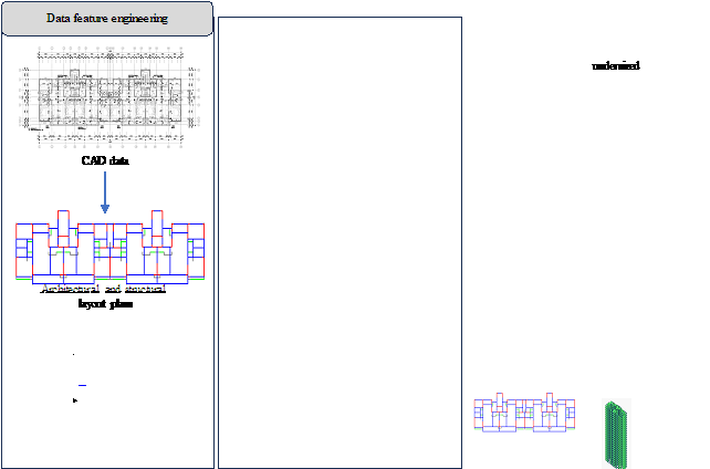
Figure 2 Method for the co-design of shear wall¨Cbeam layout schemes using GNNs
2.2 Data feature engineering
In this study, 211 computer-aided design (CAD) drawings containing complete designs of shear wall-beam structures, representing high-quality data from completed construction projects, were collected from leading design institutes across various regions of China. After cleaning, the drawings were transformed into a graph-structured dataset. The different building components in shear wall residential structures can be abstractly represented as edges and nodes, in which the nodes represent the intersection points between different edge components in a floor plan, such as walls, doors, or windows. This method of representing building components is known as graph-based edge representation [12].
The input features comprised the axis attributes of the wall and door/window component edges and the output labels comprised the axis attributes of the shear walls and beams. The GNN input and output graphs will share the same topology because shear walls must be aligned with the axes of the architectural walls; however, the attributes of the graph edges and nodes will change because beams, which are not entirely constrained by the axes of the building components, can be placed with greater spatial flexibility. Therefore, the potential topology of the beam layout must be defined in the input graph. Zhao et al. [11] introduced a method for assigning beam locations based on predefined rules in which potential beams are used to define hypothetical positions within the building space where beams may be placed, thereby limiting the possible beam locations in the final design layout.
Therefore, this study also employed a rule-based encoding method for the beam layout that can be applied to architectural space division. The integration of the potential beam layout into architectural plans allows datasets to be constructed to train the GNN. Thus, the input features for GNN training comprised graph data representing architectural walls, doors, windows, and potential beam components, whereas the output labels corresponded to the design shear wall and beam layouts. Note that as rigid-body translations do not affect the overall structural load [9,11,12], data augmentation techniques were applied to enhance training efficiency. Further details are provided in Section 3.
2.3 GNN training and evaluation
This section outlines the construction and training of the GNN model. This study employed the GraphSAGE algorithm as the core of the training process to improve the modelˇŻs ability to extract element features [31]. This algorithm combines the extracted node features with edge features through processing using a multilayer perceptron (MLP). A SoftMax function was subsequently applied to classify whether each edge represented a shear wall or beam. Finally, the influence of hyperparameters, the number of node features, and the segmentation of architectural walls on the performance of the generated designs was evaluated. Further details are provided in Section 4.
2.4 Layout optimization based on empirical rules
EngineersˇŻ design experience was not explicitly included in the preparation of the dataset or training of the GNN. Therefore, a postprocessing method was developed and applied to improve the design results by conducting local optimization and refinement of GNN-generated layouts using empirical rules coded based on engineering expertise. Further details are provided in Section 5.
3 Data feature engineering based on graph representation
3.1 Data collection
3.1.1 Preprocessing
The adopted datasets come from many design institutes in over 10 provinces in China, all of which are CAD drawings of shear wall structures. These drawings cover common architectural design scenarios. The building cases in the data cover seismic design intensities of 7 and 8 degrees, fully reflecting the diversity of seismic design and meeting the requirements of Chinese current seismic design codes. The height of the buildings ranges from 10 meters to 96 meters, covering different types of buildings from low-rise to high-rise.
The collected building design drawings were processed using the CAD data processing program developed by Fei et al. [32]. Each CAD drawing was analyzed to extract the location of architectural walls, doors, windows, shear walls, and beams, with the relevant geometric and positional attributes stored as key-value pairs in a semi-structured data format [29]. This dataset was subsequently divided into training, validation, and testing sets at an 8:1:1 ratio.
3.1.2 Potential beams
As some beams are not aligned with the axes of architectural walls, windows, or doors and are used instead to partition spaces with different functions, the beam layouts in architectural spaces are highly flexible. Based on the advice of engineers with extensive design experience and the statistical characteristics of beams shown in existing datasets, the concept of potential beams is proposed and incorporated into the architectural graph. The three-step process and associated rules for setting the potential beam axes are illustrated in Figure 3.
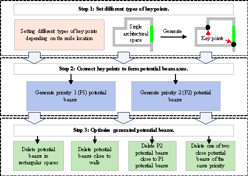
Figure 3 Potential beam axis generation process
The key points where potential beams can be constructed are determined in Step 1. Within the building outline, a node is defined as a key point if it is connected to perpendicular edges, but is missing an edge in at least one direction, excluding points on the outer walls of the building; otherwise, it is not considered a key point, as shown in Figure 4.
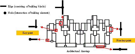
Figure 4 Schematic diagram of key points and non-key points in architectural drawings
In Step 2, the key points are connected to form potential beam axes arranged according to their relative positions. These beams are subsequently assigned priority based on the nodes they connect. Priority 1 potential beams have key points on both ends, indicating they are more likely to be located at a partition between two spaces, where they will act to divide the space. Priority 2 beams have a key point on only one end, indicating that they can be used to divide larger spaces, as shown in Figure 5.
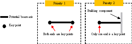
Figure 5 Definitions of priority 1 and priority 2 potential beam axes
In Step 3, the generated potential beams are optimized. Many of the potential beams defined in the previous steps are redundant, which will place high demands on the neural network training process and limit generalization performance. Therefore, redundant potential beams are removed in four stages comprising: (1) the removal of potential beams within rectangular spaces, (2) the removal of potential beams within 1000 mm of walls, (3) the removal of P2 potential beams within 1000 mm of P1 potential beams, and (4) the removal of one of two potential beams with the same priority within 500 mm of each other.
For Stage 1 removals, two parallel independent wall sections often exist on opposite sides of the same room where beams are unsuitable for dividing the space [11]; therefore, potential beam axes within a regular building space should be deleted, as shown in Figure 6(a). For Stage 2 removals, shear walls or their corresponding beams are typically arranged to transfer vertical loads; therefore, beams need not be placed near walls for load transfer and potential beams that are too close to the walls can be removed, as shown in Figure 6(b). Finally, for Stage 3 and 4 removals, one potential beam should be removed when two potential beams are close, as shown in Figure 7.
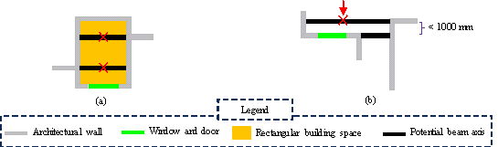
Figure 6 Optimization of potential beams: (a) delete potential beams within rectangular spaces; (b) delete potential beams that are close to nonstructural components
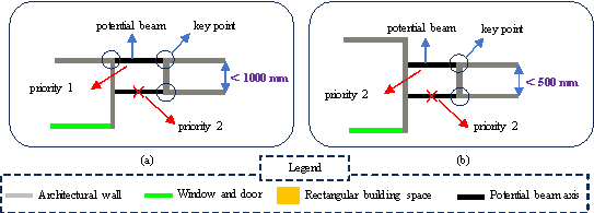
Figure 7 Optimization of potential beams when beams are close together: (a) delete the potential beam with low priority; (b) delete one potential beam with the same priority
Upon completion of this optimization process, the potential beam layout in each architectural drawing is ready for use in the intelligent co-design method. Figure 8 illustrates the overall process of generating potential beams and removing redundant instances.
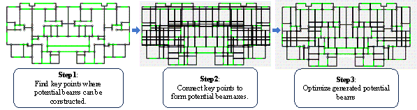
Figure 8 Generation of potential beams and removal of redundant beams
To objectively evaluate whether the arrangement
of potential beams meets the requirements of structural design, this study
use the potential beam coverage rate indicator, which measures how much of
the designed beams can be covered by the arranged mask.
![]() ,
, ![]() and
and
![]() represent the lengths of the
walls, windows and doors that can be arranged in the structure, and the potential
beams.
represent the lengths of the
walls, windows and doors that can be arranged in the structure, and the potential
beams. ![]() represents the length of the
beams. The potential beam coverage rate is calculated as shown in Equation
(1).
represents the length of the
beams. The potential beam coverage rate is calculated as shown in Equation
(1).
![]()
The potential beam coverage calculated according to this equation is 94.0%. It can be assumed that the predicted beams can reach 94.0% of the actual beam design under the condition that the best model predicts correctly at 100%. Considering that the beam design contains some randomness, even if they are all manually designed, the design results of different engineers may vary somewhat. Therefore, itˇŻs believed that 94% is sufficient and can be used for generating structures.
3.2 Graph-based data representation
3.2.1 Construction of the building graph
This study represented the structural components (shear walls and beams), nonstructural components (doors, windows, and architectural walls), and potential beams in a single graph. Architectural walls can be classified as walls that can be made into shear walls and partition walls that cannot; beams can be arranged on both nonstructural components and potential beams. To better manage the arrangement of these components, longer sections of architectural walls were divided into multiple segments using the following rules:
Ÿ Based on the patterns of the shear walls in the 211 collected drawings, architectural walls were divided into 1500 or 2000 mm segments according to their modulus lengths. Thus, the initial number of segments was determined by dividing the total length of the architectural wall by 1500 or 2000 mm.
Ÿ Three methods were used to determine the integer (final) number of segments: rounding up, rounding down, or rounding to the nearest integer.
Ÿ The final length of each segment was determined by dividing the total length of the architectural wall by the final number of segments.
The processing of an architectural drawing based on these rules is shown in Figure 9.
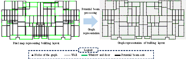
Figure 9 Segmented architectural walls and building drawing converted into a graph
3.2.2 Node features
The building and structural components were expressed in
the graph using a vectorized representation of normalized coordinates. Figure
10 illustrates the critical parameters of the architectural graph, in which
![]() and
and ![]() denote the center of the graph;
denote the center of the graph; ![]() and
and ![]() denote the maximum and minimum values in the x-direction,
respectively;
denote the maximum and minimum values in the x-direction,
respectively; ![]() and
and ![]() indicate the maximum and minimum values in the y-direction,
respectively; and
indicate the maximum and minimum values in the y-direction,
respectively; and ![]() and
and ![]() represent the span values in the y- and x-directions,
respectively.
represent the span values in the y- and x-directions,
respectively.
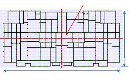
Figure 10 Parameter settings for graph element data
Equation (2) is one of the methods for calculating
the features of graph nodes. For each black point in Figure 10, its coordinates
on the corresponding CAD are ![]() , which respectively represent the
distance from the origin in the x and y directions.
, which respectively represent the
distance from the origin in the x and y directions.
![]()
![]()
![]()
where ![]() denotes the maximum span size of the image and the
feature input to the network can be represented as
denotes the maximum span size of the image and the
feature input to the network can be represented as
![]() . If the node features consisted solely of these two attributes,
they were denoted as
. If the node features consisted solely of these two attributes,
they were denoted as ![]() . However, given that GNNs can aggregate node features during
training, these features were expanded to improve the generalization capability
of the model.
. However, given that GNNs can aggregate node features during
training, these features were expanded to improve the generalization capability
of the model.
Considering the impact
of graph node features on network training, direction features were embedded
in the above-mentioned node features. The node in Figure 11 has edge
connections in four directions ( ![]() ,
, ![]() ,
, ![]() ,
, ![]() ), respectively represented as
), respectively represented as
![]() ,
, ![]() ,
, ![]() , and
, and ![]() . Thus, a four-dimensional vector
. Thus, a four-dimensional vector
![]() can be used to represent the types of edge components
connected to this node, with the value of each dimension determined using
the representation method outlined in Table 1. The application of this representation
method creates
can be used to represent the types of edge components
connected to this node, with the value of each dimension determined using
the representation method outlined in Table 1. The application of this representation
method creates ![]() with extended features, indicating that the node possesses
six attributes.
with extended features, indicating that the node possesses
six attributes.
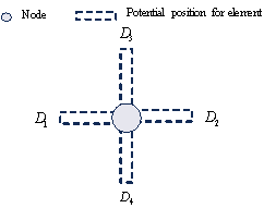
Figure 11 Graph node with edges in four directions
Table 1 Types of edge component representation methods
|
Type of component |
Blank |
Architecture wall |
Window and door |
Potential beam |
|
D1/D2/D3/D4 |
0 |
1 |
2 |
3 |
3.2.3 Edge features
Each nonstructural and structural component classified as
an edge (including architectural walls, doors and windows, shear walls, beams,
and potential beams) was represented using the coordinates ![]() and
and ![]() at each end. Initially, a one-hot encoding method was employed
to classify the graph edges for different components as detailed in Table
2.
at each end. Initially, a one-hot encoding method was employed
to classify the graph edges for different components as detailed in Table
2.
Table 2 One-hot encoding methods for different graph edge types
|
Edge type |
One hot coding method |
|
Architecture wall |
[1,0,0,0] |
|
Window and door |
[0,1,0,0] |
|
Potential beam |
[0,0,1,0] |
|
Partition wall |
[0,0,0,1] |
Furthermore, each edge was standardized in the same manner as the nodes to represent the relative positions of each component on the graph. This standardization method is given by:
![]()
where the standardized coordinate values of the edge are
represented by ![]() ,
, ![]() ,
, ![]() , and
, and ![]() .
.
Finally, the length information of the graph edges was embedded
into the edge features using a one-dimensional vector ![]() . In the process of dataset processing,
. In the process of dataset processing,
![]() is calculated according to the equation
is calculated according to the equation ![]() , where
, where ![]() represents the
represents the ![]() -th edge in the building structure, and
-th edge in the building structure, and
![]() represents the longest edge among all edges. This ensures
that all edge features have similar scales and normalization methods, thereby
promoting consistent model training process. Therefore, the
feature representation of a graph edge was expressed as
represents the longest edge among all edges. This ensures
that all edge features have similar scales and normalization methods, thereby
promoting consistent model training process. Therefore, the
feature representation of a graph edge was expressed as ![]() , forming a nine-dimensional vector, where
, forming a nine-dimensional vector, where ![]() indicates the edge classification feature determined using
one-hot encoding.
indicates the edge classification feature determined using
one-hot encoding.
3.3 Datasets and data augmentation
3.3.1 Label settings
Comparing the building diagram including potential beams to the engineer-designed structural layout, the potential beams generated by the rule-based algorithm clearly do not completely encompass all the beams designed by the engineers. Consequently, a diagram that includes the potential beams was used as a reference for labeling. During this process, a component is selected and compared with the corresponding position in the engineer-designed drawings to determine whether it is present and, if so, identify its type. If a labelable component exists at the specified position, the corresponding label is assigned; otherwise, no label is provided. This comparison was performed for each component to label the building graphs accurately using the following process:
(1) If the length of the shear wall on any segment of the architectural wall exceeds half of the segmentˇŻs total length, it is labeled as a shear wall [1, 0, 0]. Note that shear walls cannot be installed on doors, windows, or potential beams.
(2) If a beam is detected on components such as doors, windows, potential beams, and partition walls, it is labeled [0, 1, 0].
(3) Elements lacking structural components are labeled [0, 0, 1].
3.3.2 Dataset construction and data augmentation
The dataset used in this study comprised 211 preprocessed architectural graphs. These input graphs represented node features as two- or six-dimensional tensors and represented edge features as nine-dimensional tensors as described in Section 3.2. The GNN was trained on this graph dataset to predict the category of each edge in the graph, resulting in an output graph that includes shear walls and beams, as illustrated in Figure 12.
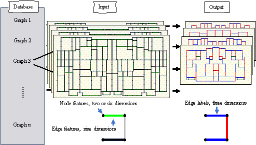
Figure 12 Composition of the GNN input dataset and output
The deep learning training process requires a substantial quantity of data. As the dataset used in this study was relatively small, common data augmentation algorithms were employed to enhance the generalization capability of the model. The data augmentation methods utilized were consistent with those described by Zhao et al. [12], wherein the arrangement of components, such as shear walls and beams, was considered independent of the translation, position, and angle of the rigid body.
Consequently, four transformation techniques were applied to augment the dataset:
Ÿ Vertical flipping (2 configurations),
Ÿ 90-degree rotation (4 configurations),
Ÿ Horizontal translation from 0 to 20 m in 2 m intervals (21 configurations)
Ÿ Vertical translation from 0 to 20 m in 2 m intervals (21 configurations).
Thus, a dataset comprising 744,408 graphs was obtained (211 ˇÁ 2 ˇÁ 4 ˇÁ 21 ˇÁ 21).
4 GNN training and testing
4.1 Model architecture
Enhancing the features of the graph edges enables the GraphSAGE algorithm to effectively capture the topological characteristics of the considered structure [12]. This is particularly critical for the co-design of shear wall and beam layouts, in which the configuration of edge features plays a vital role in the predictions and result classification. Notably, research conducted by Zhao et al. [12] demonstrated that GNN models enhanced with edge features possess significant advantages over other GNN models.
When using the edge representation method to design tall building structures with shear walls, the design of shear wall and beam layouts is conceptualized as a prediction problem for edge features within the graph representation framework. The process of predicting edge labels using the GNN comprises passing the input features through GraphSAGE algorithm layers, followed by the application of an MLP to predict the edge features using the combined feature values of each edge and its two corresponding nodes as input. Finally, the feature information for each edge is processed using a classification algorithm to yield the corresponding predicted values. This GNN structure is illustrated in Figure 13 and detailed in Table 3.
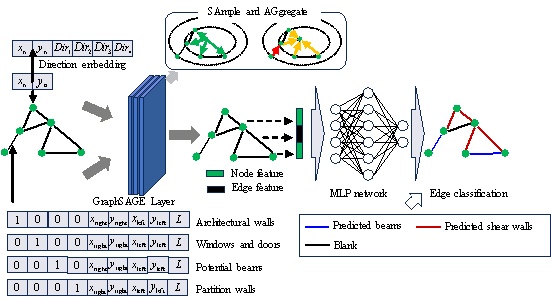
Figure 13 Feature representation method and GNN model structure
Table 3 Structure of the GNN used in this study
|
GNN Model |
|
SAGELayer (Din, 16); ReLU() |
|
SAGELayer (16, 16); ReLU() |
|
BatchNorm (16) |
|
SAGELayer (16, 32); ReLU() |
|
SAGELayer (32, 32); ReLU() |
|
BatchNorm (32) |
|
SAGELayer (32, 32); ReLU() |
|
SAGELayer (32, Dout); ReLU() |
|
Linear (2ˇÁDout + De, 32); Linear (32, 32); ReLU() |
|
BatchNorm (32) |
|
Linear (32, 16); Linear (16,16) |
In this structure, SAGELayer refers to a specific type of layer in the GNN, known as the sample and aggregate layer, which serves as a general framework for inductive node embedding. Furthermore, batch normalization (BatchNorm) is a key layer that enhances both training efficiency and network performance, addressing any numerical instability issues that arise during training by normalizing each feature vector, thereby facilitating a smoother training process. The linear or fully connected layers take the input data and apply a linear transformation to each data point by multiplying it by the corresponding weights, summing the results, then adding a bias vector to compute the output tensor.
The GNN-based graph edge classification method applied in this study employed the cross-entropy loss function, defined as follows:
![]()
where ![]() denotes the number of edge classifications, which, in this
study, included shear walls, beams, and blanks;
denotes the number of edge classifications, which, in this
study, included shear walls, beams, and blanks; ![]() denotes the total number of edge samples;
denotes the total number of edge samples; ![]() denotes the classification status of each sample, which
is 1 if the true classification of sample j is c and 0 otherwise;
and
denotes the classification status of each sample, which
is 1 if the true classification of sample j is c and 0 otherwise;
and ![]() denotes the predicted probability that sample j
belongs to class c.
denotes the predicted probability that sample j
belongs to class c.
4.2 Model training
This study optimized the hyperparameters of the network model (such as the number of layers of the GNN network, the dimension of the hidden layer, the activation function, and the regularization coefficient, etc.). The grid search method was used to evaluate the impact of different parameter combinations on the model performance on the validation data. Since the adjustment of network hyperparameters is not the focus of this study, the current dimension of the hidden layer is the optimal result selected based on its performance in IoU performance and training efficiency. The GNN model was trained using learning rates of 0.0001, 0.0005, and 0.001 along with architectural wall segmentation based on the different methods described in Section 3.2.1. Five-fold cross-validation, a commonly used method for model selection and comparison, was subsequently employed to compare the results obtained by each model and identify the optimal approach.
4.3 Analysis and discussion of intelligent design results
4.3.1 Evaluating the quality of results
The intersection over union (IoU) is widely used to assess the difference between the designs produced by AI and those produced by engineers. The application of IoU in this study was based on the work of Liao et al. [16], who demonstrated an efficient and accurate evaluation process that can quickly assess hundreds of test cases. The calculation of IoU is given by Equation (5):
![]()
where ![]() denotes the distribution of structural components (shear
walls or beams) in the engineer-designed layouts, and
denotes the distribution of structural components (shear
walls or beams) in the engineer-designed layouts, and ![]() denotes the distribution of structural components in the
GNN-generated layouts,
denotes the distribution of structural components in the
GNN-generated layouts, ![]() denotes the AND operation performed on the Boolean pixel
map and
denotes the AND operation performed on the Boolean pixel
map and ![]() denotes the OR operation performed on the Boolean pixel
map.
denotes the OR operation performed on the Boolean pixel
map.
4.3.2 Comparison and evaluation of design results
Figure 14 compares three structural layouts designed by engineers with similar layouts generated by the GNN-based intelligent design method proposed in this study. In this illustration, red represents shear walls, blue indicates beams, gray represents architectural walls, and green represents door/window components. The comparison indicates that the intelligent co-design method achieved notable improvements in the local layouts of components, such as the arrangement of shear walls at the corners of the building's exterior profile. In terms of component continuity, the proposed method clearly ensured that both the shear walls and beams remained connected in most scenarios. Notably, the IoU values for the majority of cases exceeded 0.5, indicating a high degree of similarity between the GNN-generated and engineer-designed layouts. These results validate the effectiveness of the proposed approach for generating potential shear wall and beam layouts.
Furthermore, the comparison presented in Figure 14 suggests that the GNN effectively captured the wall¨Cbeam topological relationships present in shear wall structures. To address instances where the results may be less satisfactory, such as the layout in Case 3, which did not comply with certain engineering empirical rules, such as placing shear walls on the balcony, this study developed an optimization method to regularize the model output, thereby ensuring the reliability of the intelligent design algorithm. This method is presented in Section 5.
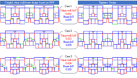
Figure 14 Comparison between GNN-generated and engineer-designed layouts
Next, the effects of learning rate (discussed in Section
4.2), node feature number (where ![]() and
and ![]() indicate six and two features, respectively), initial segment
length (where
indicate six and two features, respectively), initial segment
length (where ![]() and
and ![]() denote segment lengths of 1500 and 2000 mm, respectively),
and rounding method (where
denote segment lengths of 1500 and 2000 mm, respectively),
and rounding method (where ![]() represents rounding up,
represents rounding up, ![]() represents rounding down, and
represents rounding down, and ![]() represents rounding to the nearest integer) on the performance
of the model were evaluated in terms of the shear wall IoU (SIoU) and beam
IoU (BIoU), with the results summarized in Tables 4 and 5, respectively. For
the three columns of data corresponding to "Learning rate" in the
table, the number before the symbol "
represents rounding to the nearest integer) on the performance
of the model were evaluated in terms of the shear wall IoU (SIoU) and beam
IoU (BIoU), with the results summarized in Tables 4 and 5, respectively. For
the three columns of data corresponding to "Learning rate" in the
table, the number before the symbol " ![]() " represents the mean of the sample, and
the number after it represents the upper and lower limits of the corresponding
values of the 95% confidence interval. As the actual
length of each shear wall segment was calculated considering the varying lengths
of the architectural walls, the initial segment length and rounding method
are collectively referred to as the wall segment division to realize a unified
analysis.
" represents the mean of the sample, and
the number after it represents the upper and lower limits of the corresponding
values of the 95% confidence interval. As the actual
length of each shear wall segment was calculated considering the varying lengths
of the architectural walls, the initial segment length and rounding method
are collectively referred to as the wall segment division to realize a unified
analysis.
The calculated SIoUs indicate that the network trained with
embedded node directional features ( ![]() ) demonstrated a significantly better fitting performance than that
trained solely with node coordinate features (
) demonstrated a significantly better fitting performance than that
trained solely with node coordinate features ( ![]() (metric
(metric ![]() ). In addition, the SIoUs obtained using
). In addition, the SIoUs obtained using ![]() superior to those obtained using
superior to those obtained using ![]() . Indeed, this segmentation directly affected the shear wall layout
because both endpoints must explicitly consider the surrounding environmental
information, and a longer initial wall segment reduced the loss associated
with each segment during network training. Moreover, an increased number of
node features enhanced the sensitivity of the shear wall layout to the surrounding
environment, leading to improved results. Notably, the GraphSAGE algorithm
applied in this study required denser nodes for effective network learning.
Thus, a higher number of nodes resulted in improved learning outcomes. Finally,
a learning rate of 0.001 yielded better network fitting results when generating
shear walls using the proposed method.
. Indeed, this segmentation directly affected the shear wall layout
because both endpoints must explicitly consider the surrounding environmental
information, and a longer initial wall segment reduced the loss associated
with each segment during network training. Moreover, an increased number of
node features enhanced the sensitivity of the shear wall layout to the surrounding
environment, leading to improved results. Notably, the GraphSAGE algorithm
applied in this study required denser nodes for effective network learning.
Thus, a higher number of nodes resulted in improved learning outcomes. Finally,
a learning rate of 0.001 yielded better network fitting results when generating
shear walls using the proposed method.
Beams were primarily arranged above the door and window
components, at potential beam locations, and at architectural walls other
than shear walls, which means that the shear wall segmentation length did
not significantly influence the beam arrangement. According to the
![]() BIoU results, the use of six node features (
BIoU results, the use of six node features ( ![]() slightly diminished the beam arrangement quality because the distinction
between the endpoint node information for beams was often simpler than that
for shear walls. Consequently, the network sacrificed some degree of quality
in the beam arrangement to optimize the shear wall layout, thereby achieving
a coordinated layout for both components. Learning rates of 0.0005 and 0.001
both yielded satisfactory results when arranging the beams using the proposed
method.
slightly diminished the beam arrangement quality because the distinction
between the endpoint node information for beams was often simpler than that
for shear walls. Consequently, the network sacrificed some degree of quality
in the beam arrangement to optimize the shear wall layout, thereby achieving
a coordinated layout for both components. Learning rates of 0.0005 and 0.001
both yielded satisfactory results when arranging the beams using the proposed
method.
Table 4 Calculated SIoU values using different node features, wall segment divisions, and learning rates
|
Number of node features |
Length of wall section |
Rounding method |
Learning rate |
Mean IoU of segment mode (M2) |
Mean IoU of node features (M1) |
||
|
0.0001 |
0.0005 |
0.001 |
|||||
|
N6 |
L1.5 |
R0 |
0.599 |
0.643 |
0.650 |
0.654 |
0.657* |
|
R1 |
0.646 |
0.660 |
0.654 |
||||
|
R2 |
0.614 |
0.682 |
0.636 |
||||
|
L2 |
R0 |
0.616 |
0.634 |
0.652 |
0.660* |
||
|
R1 |
0.639 |
0.654 |
0.689 |
||||
|
R2 |
0.622 |
0.667 |
0.666 |
||||
|
N2 |
L1.5 |
R0 |
0.637 |
0.630 |
0.639 |
0.642 |
0.647 |
|
R1 |
0.634 |
0.663 |
0.625 |
||||
|
R2 |
0.624 |
0.644 |
0.654 |
||||
|
L2 |
R0 |
0.592 |
0.640 |
0.648 |
0.652* |
||
|
R1 |
0.636 |
0.648 |
0.654 |
||||
|
R2 |
0.650 |
0.646 |
0.674 |
||||
|
Mean IoU of learning rate (M3) |
0.626 |
0.651 |
0.653* |
||||
Table 5 Calculated BIoU values using different node features, wall segment divisions, and learning rates
|
Number of node features |
Length of wall section |
Rounding method |
Learning rate |
Mean IoU of segment mode(M2) |
Mean IoU of node features(M1) |
||
|
0.0001 |
0.0005 |
0.001 |
|||||
|
N6 |
L1.5 |
R0 |
0.630 |
0.636 |
0.642 |
0.650 |
0.655 |
|
R1 |
0.646 |
0.652 |
0.653 |
||||
|
R2 |
0.631 |
0.671 |
0.685 |
||||
|
L2 |
R0 |
0.655 |
0.662 |
0.664 |
0.661* |
||
|
R1 |
0.648 |
0.661 |
0.657 |
||||
|
R2 |
0.666 |
0.676 |
0.659 |
||||
|
N2 |
L1.5 |
R0 |
0.658 |
0.674 |
0.673 |
0.660* |
0.656* |
|
R1 |
0.644 |
0.664 |
0.666 |
||||
|
R2 |
0.635 |
0.665 |
0.658 |
||||
|
L2 |
R0 |
0.637 |
0.664 |
0.664 |
0.653 |
||
|
R1 |
0.630 |
0.653 |
0.646 |
||||
|
R2 |
0.638 |
0.668 |
0.680 |
||||
|
Mean IoU of learning rate(M3) |
0.643 |
0.662* |
0.662* |
||||
Taking the model trained with 6 node features, 2 m wall segment length, and R_2 as an example, the box plots of SIoU and BIoU are plotted, as shown in Figure 15. In the co-design task, the model has a better learning effect on beam layout than shear wall layout. The reason is that the network used in this task is the GraphSAGE network, and the learning of node features is significantly enhanced. When arranging beams, the situation of components already arranged at the nodes is considered, so it is more dependent on node features, with better effect.
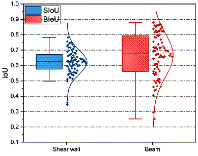
Figure 15 Comparison of SIoU and BIoU of the model results trained
with 6 node features, 2 m wall segment length, and
![]() rounding method
rounding method
5 Postprocessing of GNN-generated layouts based on rule encoding
Some of the GNN-generated structural component layouts obtained in Section 4 failed to comply with the specification requirements for structural arrangements. Moreover, some locations where shear walls need to be arranged were not noticed by the AI. A post-processing method based on the rules of engineers' experience was proposed. Situations where such optimization of shear wall arrangements is necessary were addressed in this study by adopting the methodology presented by Qin et al. [29] to enhance the shear wall layouts in terms of topology, pattern, and dimensions. This optimization algorithm modifies both the shear wall and beam arrangements to comply with the empirical rules of structural design using three sub-processes, as illustrated in Figure 15.
(1) Insertion of shear walls in the middle of long beams (Figure 16(a)): According to Zhao et al. [22], when the span of a beam exceeds 6 m, additional shear walls must be provided near the center of the beam. These inserted shear walls are typically arranged in self-stabilizing configurations, such as L- or T-shaped layouts.
(2) Deletion of redundant secondary beams (Figure 16(b)): Rectangular architectural spaces are identified within the building structures and unnecessary secondary beams located between two rectangular spaces are subsequently removed.
(3) Addition of shear walls when transverse beams are non-collinear (Figure 16(c)): When the distance between two parallel, non-colinear beams on either side of an orthogonal beam is less than 200 mm, an L-shaped shear wall is added if a suitable position for one exists.
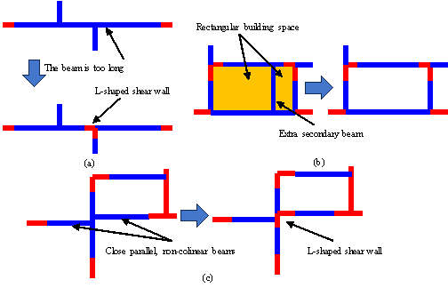
Figure 16 Details of the shear wall and beam layout optimization method showing (a) handling of overlong beams, (b) removal of redundant secondary beams, and (c) optimization at parallel, non-colinear beams
An GNN design case presenting the presence of long beams, unreasonable arrangements of secondary beams, and non-colinear beams was applied in this study to illustrate the effects of these optimization methods with the results shown in Figure 17.
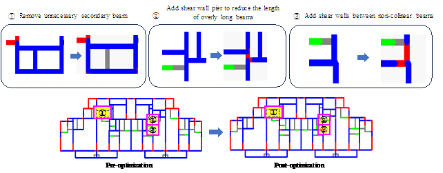
Figure 17 Results of the optimization process
6 Case study
6.1 Basic information
A typical residential building designed by a prominent design institute in China was selected as a case study. This building has a height of 75 m comprising 25 stories above ground. Its seismic design intensity is classified as VIII with a peak ground acceleration for basic seismic design of 0.20g and a 50-year exceedance probability of 10%. The site is categorized as Class II (indicating that the soil layer is relatively stable and not as prone to seismic wave amplification effects as soft soil) and falls into Seismic Group 2 (corresponding to moderate earthquake risk based on seismic zoning maps and site conditions). The building has a characteristic period of 0.4 s, is rated for Grade III seismic resistance (indicating that the building meets the earthquake resistance requirements for ordinary residential buildings), and is assigned Category C fortification (indicating that the importance of the building is average).
6.2 Intelligent design process
Figure 18 compares layouts generated by the proposed GNN-based co-design, actual engineerˇŻs design, and conventional successive shear wall and beam design using independent GNN models. The SIoU and BIoU obtained using the proposed co-design method were 0.625 and 0.548, respectively, whereas those obtained using the successive design method were 0.544 and 0.404, respectively. Thus, the proposed co-design method improved the shear wall and beam layout design performance by 14.9% and 35.6%, respectively, compared with the conventional successive design method. This shows that by simultaneously considering the layout of shear walls and beams through graph neural networks and capturing the topological relationship between the two, the interdependence of shear walls and beams can be optimized in the same process. This method eliminates the information fragmentation in the existing sequential design and can more accurately reflect the complex interactions between structural components, thereby improving the overall performance and efficiency of the design.
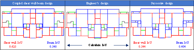
Figure 18 Comparison of case study design results
Structural analysis is a reliable approach for quantifying the performance of a design. Before performing structural analysis, the floor slabs must be arranged on and loads applied to the structural component layout comprising the shear walls and beams. This study utilized the AIStructure application programming interface (API) [30] to realize the rapid arrangement of floor slabs and application of loads to the beams and slabs. Subsequently, the PKPM API software development tool was employed to achieve automated structural modeling and mechanical analysis. The entire process is illustrated in Figure 19.
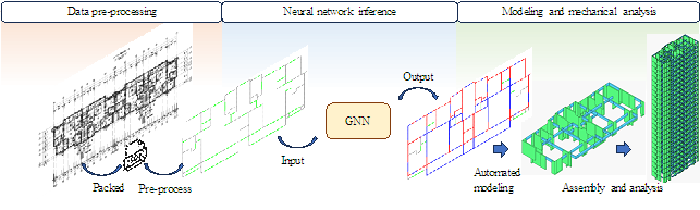
Figure 19 Intelligent design and analysis process
6.3 Structural analysis results and comparison
The advantages of the proposed intelligent co-design method for generating wall and beam layouts were demonstrated in this study by comparing the performances of structures obtained by the proposed GNN-based co-design method, competent engineers, and the conventional independent GNN-based successive design method.
The results presented in Table 6 and Figure 19 reveal that the proposed co-design method produced satisfactory outcomes for the case study building. All calculated structural performance metrics remained within the limits set by the specifications, and the inter-story drift ratio in the x-direction was even superior to that of the engineer-designed structure. In contrast, the results obtained using the conventional successive design method exceeded the specified limits for both the shear-to-weight ratios and maximum inter-story drift ratios. The success of the proposed intelligent co-design method stems from its ability to consider the topological relationship between the shear wall and beam layouts, which are designed concurrently during the generation and optimization processes. In contrast, the conventional method of first designing shear walls, then beams considers each component type separately, reducing the understanding of their interdependence. Indeed, the inter-story drift ratios obtained by conventional successive design method were 37.05% and 76.00% higher in the x- and y-directions, respectively, than those obtained by the co-design method, highlighting the inferior performance of the conventional approach.
According to the calculation results of material usage in Table 6, compared with the method of designing shear walls and beams sequentially, the material consumption of steel and concrete used in this study was reduced by 7.73% and 6.65% respectively, which significantly saved material usage and was also closer to the design results of engineers. Since the engineerˇŻs design results selected in this article are based on the results of a large number of optimized designs by China's top design institutes, the material usage is close to the optimal value, so the material usage given by the AI co-design is slightly higher than the engineerˇŻs design. In the future, the economy can be improved through further optimization of the design.
This shows that the co-design method effectively considers the topology between the shear wall and the beam during the design process, and meets the structural design requirements while reducing material usage. In terms of design efficiency, the entire process of completing intelligent design and modeling only takes 20 to 30 seconds with this research method, while the sequential design method requires more time because it needs to carry out two model inferences successively. Compared with the engineer's design method, the design efficiency of intelligent design has been improved by more than 30 times, which has achieved quite remarkable results.
Table 6 Comparison of results obtained using three design methods
|
Structural indicators |
This study |
EngineerˇŻs design |
Successive design |
|
|
Period (s) |
1st order |
1.66 |
1.59 |
2.12 |
|
2nd order |
1.36 |
1.57 |
1.91 |
|
|
3rd order |
0.87 |
0.96 |
1.14 |
|
|
Periodic ratio |
0.53 |
0.61 |
0.54 |
|
|
Maximum inter-story drift ratio (rad) |
x-direction |
1/1621 |
1/1321 |
1/1163 |
|
y-direction |
1/1276 |
1/1253 |
1/931* |
|
|
Shear-to-weight ratio (%) |
x-direction |
3.92 |
4.12 |
3.20*(modified) |
|
y-direction |
4.24 |
4.30 |
3.52 |
|
|
Rigidity-to-weight ratio |
x-direction |
11.66 |
7.44 |
6.81 |
|
y-direction |
6.70 |
7.19 |
4.16 |
|
|
Material consumption |
Concrete (
|
1787.8 |
1723.3 |
1915.2 |
|
Steel (kg) |
172.56 |
155.40 |
187.02 |
|
|
Comparison of design efficiency |
20 ~ 30 s |
30 min |
30 ~ 50 s |
|
* Indicates that the value exceeds the specified limit (i.e., 1/1000)
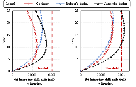
Figure 20 Inter-story drift ratios of three structural designs
7 Conclusion
This study proposed and demonstrated a method for the GNN-based intelligent co-design of shear wall and beam layouts. The initial architectural data were subjected to a rule-based preprocessing stage that identified potential beams to construct a building graph. Subsequently, a GraphSAGE-based GNN model was trained to simultaneously generate the shear wall and beam layouts. Finally, empirical rule encoding was applied to optimize the generated output. This approach enabled the rapid co-design of shear wall and beam layouts while ensuring compliance with various specifications. The key conclusions of this study are as follows:
(1) The proposed method for generating potential beams in architectural drawings was based on empirical design rules to not only restrict beam generation to possible locations, but also offer multiple plausible beam positions, increasing the diversity of options for the generated outputs.
(2) Two initial wall segment lengths of 1500 or 2000 mm were evaluated when preparing the graph data. This segmentation approach allowed the generation of both shear walls and beams as components of architectural walls. The use of shorter graph edge segments enhanced the sampling depth of node features when embedded into neighboring nodes, thereby improving the overall effectiveness of the graph representation.
(3) The GraphSAGE algorithm utilized in the GNN model enhanced the extraction and embedding of graph node features, demonstrating improved performance, particularly in the generation of shear wall layouts when the node features were dense. The IoU values calculated for the shear walls and beams in the GNN-generated layouts were above 0.5, indicating that the generated designs closely resembled the designs produced by engineers. This further validates the feasibility of the proposed method.
(4) Finally, this study developed a rule-based encoding method for the joint optimization of shear wall and beam layouts to enhance the structural performance of the GNN-generated results. Structural analyses of a case study building indicated that the proposed intelligent co-design and optimization method produced shear wall and beam layouts that met all the specified criteria and significantly surpassed the traditional approach of successively arranging shear walls and beams using independent GNNs.
Although case studies show that the algorithms of co-design have achieved good results, considering that the generation of beams depends on the arrangement of potential beams, it is still necessary to explore better methods for generating potential beams, such as introducing more engineering experience rules and hard-coding rules, to further optimize the generation of potential beams. And many image-based generative algorithms such as the diffusion model and VAR (Visual Autoregression) have shown good performance. In future work, specific methods for representing images on walls and beams will be further considered to explore a representation route that is more suitable for the co-design method and improve the efficiency of intelligent design. Also, Future work should enhance the GNN dataset construction methods and refine the intelligent design algorithms to improve the calculated IoU for the shear wall and beam layouts. Moreover, streamlining the rule-based encoding methods applied in the postprocessing stage could further enhance the performance and efficiency of the proposed intelligent co-design approach.
Acknowledgements
References
[1] S. El-Tawil, K.A. Harries, P.J. Fortney, B.M. Shahrooz, Y. Kurama, Seismic design of hybrid coupled wall systems: State of the art, J. Struct. Eng. 136 (2010) 755¨C769. https://doi.org/10.1061/(ASCE)ST.1943-541X.0000186.
[2] W.J. Liao, X.Z. Lu, Y.F. Fei, Y. Gu, Y. Huang, Generative AI design for building structures, Autom. Constr. 157 (2024) 105187. https://doi.org/10.1016/j.autcon.2023.105187.
[3] P.N. Pizarro, L.M. Massone, F.R. Rojas, R.O. Ruiz, Use of convolutional networks in the conceptual structural design of shear wall buildings layout, Eng. Struct. 239 (2021) 112311. https://doi.org/10.1016/j.engstruct.2021.112311.
[4] P.N. Pizarro, L.M. Massone, Structural design of reinforced concrete buildings based on deep neural networks, Eng. Struct. 241 (2021) 112377. https://doi.org/10.1016/j.engstruct.2021.112377.
[5] Y. Zhang, C. Mueller, Shear wall layout optimization for conceptual design of tall buildings, Eng. Struct. 140 (2017) 225¨C240. https://doi.org/10.1016/j.engstruct.2017.02.059.
[6] I.J. Goodfellow, J. Pouget-Abadie, M. Mirza, B. Xu, D. Warde-Farley, S. Ozair, A. Courville, Y. Bengio, Generative adversarial networks, (2014). http://arxiv.org/abs/1406.2661 (accessed September 22, 2024).
[7] N. Nauata, K.-H. Chang, C.-Y. Cheng, G. Mori, Y. Furukawa, House-GAN: Relational generative adversarial networks for graph-constrained house layout generation, in: A. Vedaldi, H. Bischof, T. Brox, J.-M. Frahm (Eds.), Comput. Vis. ¨C ECCV 2020, Springer International Publishing, Cham, 2020: pp. 162¨C177.
[8] N. Nauata, S. Hosseini, K.-H. Chang, H. Chu, C.-Y. Cheng, Y. Furukawa, House-GAN++: Generative adversarial layout refinement network towards intelligent computational agent for professional architects, in: 2021 IEEECVF Conf. Comput. Vis. Pattern Recognit. CVPR, IEEE, Nashville, TN, USA, 2021: pp. 13627¨C13636. https://doi.org/10.1109/CVPR46437.2021.01342.
[9] Y. Gu, Y.L. Huang, W.J. Liao, X.Z. Lu, Intelligent design of shear wall layout based on diffusion models, Comput.-Aided Civ. Infrastruct. Eng. (2024). https://doi.org/10.1111/mice.13236.
[10] Y. Zhou, H. Leng, S. Meng, H. Wu, Z. Zhang, StructDiffusion: End-to-end intelligent shear wall structure layout generation and analysis using diffusion model, Eng. Struct. 309 (2024) 118068. https://doi.org/10.1016/j.engstruct.2024.118068.
[11] P.J. Zhao, W.J. Liao, Y.L. Huang, X.Z. Lu, Beam layout design of shear wall structures based on graph neural networks, Autom. Constr. 158 (2024) 105223. https://doi.org/10.1016/j.autcon.2023.105223.
[12] P.J. Zhao, W.J. Liao, Y.L. Huang, X.Z. Lu, Intelligent design of shear wall layout based on graph neural networks, Adv. Eng. Inform. 55 (2023) 101886. https://doi.org/10.1016/j.aei.2023.101886.
[13] P.J. Zhao, W.J. Liao, Y.L. Huang, X.Z. Lu, Intelligent beam layout design for frame structure based on graph neural networks, J. Build. Eng. 63 (2023) 105499. https://doi.org/10.1016/j.jobe.2022.105499.
[14] P.J. Zhao, Y.F. Fei, Y.L. Huang, Y.T. Feng, W.J. Liao, X.Z. Lu, Design-condition-informed shear wall layout design based on graph neural networks, Adv. Eng. Inform. 58 (2023) 102190. https://doi.org/10.1016/j.aei.2023.102190.
[15] W.J. Liao, X.Y. Wang, Y.F. Fei, Y.L. Huang, L.L. Xie, X.Z. Lu, Base©\isolation design of shear wall structures using physics©\rule©\co©\guided self©\supervised generative adversarial networks, Earthq. Eng. Struct. Dyn. 52 (2023) 3281¨C3303. https://doi.org/10.1002/eqe.3862.
[16] W.J. Liao, X.Z. Lu, Y.L. Huang, Z. Zheng, Y.Q. Lin, Automated structural design of shear wall residential buildings using generative adversarial networks, Autom. Constr. 132 (2021) 103931. https://doi.org/10.1016/j.autcon.2021.103931.
[17] W.J. Liao, Y.L. Huang, Z. Zheng, X.Z. Lu, Intelligent generative structural design method for shear wall building based on ˇ°fused-text-image-to-imageˇ± generative adversarial networks, Expert Syst. Appl. 210 (2022) 118530. https://doi.org/10.1016/j.eswa.2022.118530.
[18] X.Z. Lu, W.J. Liao, Y. Zhang, Y.L. Huang, Intelligent structural design of shear wall residence using physics©\enhanced generative adversarial networks, Earthq. Eng. Struct. Dyn. 51 (2022) 1657¨C1676. https://doi.org/10.1002/eqe.3632.
[19] C. Zhang, M. Tao, C. Wang, J. Fan, End©\to©\end generation of structural topology for complex architectural layouts with graph neural networks, Comput.-Aided Civ. Infrastruct. Eng. 39 (2024) 756¨C775. https://doi.org/10.1111/mice.13098.
[20] K.-H. Chang, C.-Y. Cheng, Learning to simulate and design for structural engineering, in: Proc. 37th Int. Conf. Mach. Learn., PMLR, 2020: pp. 1426¨C1436. https://proceedings.mlr.press/v119/chang20a.html (accessed September 24, 2024).
[21] A. Nimtawat, P. Nanakorn, Automated layout design of beam-slab floors using a genetic algorithm, Comput. Struct. 87 (2009) 1308¨C1330. https://doi.org/10.1016/j.compstruc.2009.06.007.
[22] P.J. Zhao, W.J. Liao, H.J. Xue, X.Z. Lu, Intelligent design method for beam and slab of shear wall structure based on deep learning, J. Build. Eng. 57 (2022) 104838. https://doi.org/10.1016/j.jobe.2022.104838.
[23] P.J. Zhao, W.J. Liao, Y.L. Huang, X.Z. Lu, Intelligent design of shear wall layout based on attention-enhanced generative adversarial network, Eng. Struct. 274 (2023) 115170. https://doi.org/10.1016/j.engstruct.2022.115170.
[24] A. Nimtawat, P. Nanakorn, Simple particle swarm optimization for solving beam-slab layout design problems, Procedia Eng. 14 (2011) 1392¨C1398. https://doi.org/10.1016/j.proeng.2011.07.175.
[25] Y. Sun, H. Li, M. Shabaz, A. Sharma, Research on building truss design based on particle swarm intelligence optimization algorithm, Int. J. Syst. Assur. Eng. Manag. 13 (2022) 38¨C48. https://doi.org/10.1007/s13198-021-01192-x.
[26] S. Boonstra, K. Van Der Blom, H. Hofmeyer, M.T.M. Emmerich, Hybridization of an evolutionary algorithm and simulations of co-evolutionary design processes for early-stage building spatial design optimization, Autom. Constr. 124 (2021) 103522. https://doi.org/10.1016/j.autcon.2020.103522.
[27] X. Zhou, L. Wang, J. Liu, G. Cheng, D. Chen, P. Yu, Automated structural design of shear wall structures based on modified genetic algorithm and prior knowledge, Autom. Constr. 139 (2022) 104318. https://doi.org/10.1016/j.autcon.2022.104318.
[28] Y.F. Fei, W.J. Liao, X.Z. Lu, E. Taciroglu, H. Guan, Semi-supervised learning method incorporating structural optimization for shear-wall structure design using small and long-tailed datasets, J. Build. Eng. 79 (2023) 107873. https://doi.org/10.1016/j.jobe.2023.107873.
[29] S.Z. Qin, H. Guan, W.J. Liao, Y. Gu, Z. Zheng, H.J. Xue, X.Z. Lu, Intelligent design and optimization system for shear wall structures based on large language models and generative artificial intelligence, J. Build. Eng. 95 (2024) 109996. https://doi.org/10.1016/j.jobe.2024.109996.
[30] S.Z. Qin, W.J. Liao, S.N Huang, K.G. Hu, Z. Tan, Y. Gao, X.Z. Lu, AIstructure-copilot: Assistant for generative AI-driven intelligent design of building structures, Smart Constr. (2024). https://doi.org/10.55092/sc20240001.
[31] W.L. Hamilton, R. Ying, J. Leskovec, Inductive representation learning on large graphs, (2018). http://arxiv.org/abs/1706.02216 (accessed September 22, 2024).
[32] Y.F. Fei, W.J. Liao, S. Zhang, P.F. Yin, B. Han, P.J. Zhao, X.Y. Chen, X.Z. Lu, Integrated schematic design method for shear wall structures: A practical application of generative adversarial networks, Buildings 12 (2022) 1295. https://doi.org/10.3390/buildings12091295.