Abstract
Traditional architectural and structural design workflows often require repetitive manual operations. Although recent artificial intelligence methods have advanced floor plan generation and structural design, most studies focus on isolated subtasks and simple residential datasets, limiting their applicability to detached houses. This study develops an AI-assisted sequential generative workflow for preliminary architectural and structural design of detached houses. For floor plan generation, a transfer learning strategy is adopted, in which the model is pretrained on RPLAN and then fully fine-tuned on a self-collected dataset of detached houses. For architectural component generation and frame column placement, binary feature tensors are constructed as condition representations to encode the results generated by upstream models. Beam layout generation, member sizing, and PKPM-based verification are further connected through existing modular structural design methods. Quantitative results show that the workflow achieves a Micro IoU of 0.6165 for floor plan generation, a Micro IoU of 0.7479 for architectural component generation, and an IoU of 0.7885 for frame column placement. Three case studies successfully passed PKPM-based seismic code verification and reduced preliminary design time by approximately 91% compared with conventional manual workflows, demonstrating the potential engineering applicability and efficiency improvement capability of the proposed workflow. It is worthy to note that the current validation is limited by the small dataset, manual refinement between stages, case-based verification, and limited seismic design scenarios.
Keywords: Generative design, diffusion models, architectural and structural design, detached houses, transfer learning
1 Introduction
Artificial intelligence and computational design are increasingly reshaping architectural, structural, and civil engineering design by supporting the interpretation of requirements, generative design exploration, and automated design (Castro Pena et al., 2021; Kim et al., 2024; Sherif et al., 2022). Recent studies have explored the use of machine learning, including graph neural networks, generative adversarial networks, diffusion models, and large language models to generate building layouts, structural components, and design alternatives from requirements, geometric boundaries, room adjacency relationships, or engineering constraints (Mostafavi et al., 2024; Newton, 2019; Chang et al., 2021; He et al., 2025; Qin et al., 2024; Nyokum et al., 2025). These studies demonstrate the potential of AI-assisted design to reduce repetitive modeling work and support early-stage design exploration. However, real building design is not a single-step generation task. It involves a continuous process from architectural requirements to floor plan layout, architectural component layout, structural column and beam layout, member section sizing, and structural performance verification. Therefore, a key challenge is not only how to generate individual design outputs, but also how to connect architectural and structural information across different design stages through consistent data representations and workflow interfaces.
Architectural floor plan generation has been widely studied as an important subtask of automated design. Early data-driven and procedural methods attempted to generate residential layouts from boundary conditions, room programs, and spatial constraints (Merrell et al., 2010; Wu et al., 2019; Lopes et al., 2010; Rodrigues et al., 2013). More recent studies have introduced graph-conditioned generation, relational generative adversarial networks, vectorized layout generation, Transformer-based refinement, diffusion models, and language-guided generation to improve controllability, diversity, and geometric consistency (Hu et al., 2020; Nauata et al., 2020; Nauata et al., 2021; Liu et al., 2022; Shabani et al., 2023; Leng et al., 2023; Qin et al., 2024; Takeuchi et al., 2024). These works have significantly advanced automated floor plan generation. Nevertheless, most of them treat the room layout itself as the final output and mainly focus on single floor or apartment residential plans. In real design workflows, floor plans must be followed by architectural component placement, including walls, doors, windows, and open spatial dividers, and must eventually be connected to structural column and beam layout. Existing floor plan generation studies, therefore, provide an important foundation, but they do not directly support a complete architectural and structural design process.
In parallel, AI-assisted structural design has also received growing attention. Existing studies have explored intelligent shear wall layout generation, structural component layout, member section sizing, BIM-assisted structural design, topology optimization, and structural design assistants (Liao et al., 2022; Zhao et al., 2023; Fei et al., 2022; Gu et al., 2024; Zhou et al., 2024; Qin et al., 2025; He et al., 2025; Málaga-Chuquitaype, 2022). These studies show that data-driven methods can learn engineering design experience and improve efficiency in specific structural design subtasks. However, most AI-based structural design methods assume that architectural information has already been given, simplified, or manually prepared. They typically focus on a single structural subtask and do not address how architectural floor plans are generated or how architectural outputs can be converted into structural design constraints. Consequently, a clear gap remains between architectural floor plan generation and AI-based structural design.
However, real-world detached house data remain limited in scale, which constrains further improvement and large-scale application of data-driven generative methods in engineering practice. Transfer learning has been widely adopted in data-limited engineering applications where large source-domain datasets are available (Pan and Yang, 2010; Zhuang et al., 2020). By first learning general representations from large datasets and then adapting them to domain-specific tasks, transfer learning can reduce the dependence on extensive target-domain data while preserving task-relevant knowledge. Nevertheless, its application to detached house floor plan generation under limited real-world data remains insufficiently investigated.
Based on the above discussion, four limitations still remain to be addressed. (1) Existing floor plan generation studies mainly focus on isolated layout generation and lack a continuous AI-assisted architectural and structural generative workflow for a complete design object. (2) There is still no preliminary detached house architectural and structural dataset available for preliminary validation. (3) Real detached house design data are limited in scale, making it difficult to train high-capacity generative models from scratch, while the transfer adaptation from large-scale residential layout datasets to limited real detached house datasets has not been systematically validated. (4) Existing AI-based architectural and structural design methods mainly focus on individual subtasks and lack a unified data flow representation for inter-stage information transfer.
To address these issues, this study develops an AI-assisted sequential architectural and structural generative workflow for the preliminary design of detached houses. Given structured design requirements and building outlines, the workflow progressively connects floor plan generation, architectural component layout generation, frame column and beam layout generation, member section sizing, and structural performance verification. The main contributions of this study are summarized as follows:
(2) A cross-stage representation and conditioning scheme is established to connect architectural and structural generation tasks that originally use heterogeneous input and output representations. Floor plans, architectural components, and structural information are progressively converted into multi-channel binary feature tensors and task-specific masks, allowing upstream architectural information to act explicitly as geometric and semantic constraints for downstream generation.
(3) Existing generative backbones are adapted to the detached house design tasks rather than directly concatenated as independent modules. ChatHouseDiffusion is adapted through full-parameter transfer learning under limited target-domain data, while Struct-diffusion is reformulated for architectural component and frame column generation using task-specific targets, condition tensors, masks, and column representations. Ablation experiments demonstrate the contribution of these adapted representations and cross-stage constraints.
(4) The resulting modules are integrated with existing beam layout generation, member sizing, and PKPM verification methods to establish and preliminarily validate an AI-assisted architectural and structural design workflow. Three case studies are used to evaluate the feasibility and potential efficiency improvement of the workflow, while manual refinement and cross-floor coordination are explicitly retained where automated modeling remains insufficient.
2 Diffusion Model-Based Sequential Architectural and Structural Generative Design Workflow
This study proposes a diffusion model-based sequential architectural and structural generative design workflow for detached houses. The overall process is shown in Figure 1.
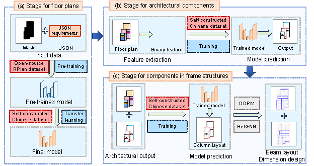
Figure 1. The proposed diffusion model-based sequential architectural and structural generative design workflow.
2.1 Conditional diffusion model formulation
Floor plan generation,
architectural component layout generation, and frame column layout generation
are all formulated as conditional denoising diffusion processes. In these
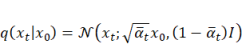
stages, the target design representation is denoted as  , the forward diffusion process gradually perturbs
  by adding Gaussian noise:
 (1)
(1)
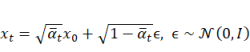
where t denotes the diffusion step and  . Equivalently,
  can be sampled as:
 (2)
(2)
The reverse process learns to recover the target representation from the noisy sample under a task-specific condition c:
 (3)
(3)
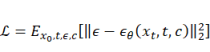
The denoising network is trained to predict the noise added in the forward process by minimizing:
 (4)
(4)
In this study, the condition c is defined according to the input requirements of each stage. For floor plan generation, c includes the structured design requirements and building outline. For architectural component layout generation, c consists of room binary feature tensors. For frame column layout generation, c is constructed from the generated floor plan and architectural component tensors. Therefore, the three diffusion-based stages follow the same conditional denoising formulation, while differing in the construction of the condition representation and the target design output.
2.2 Architectural Floor Plan Generation
This stage focuses on adapting floor plan generation to the self-collected detached house dataset with limited target-domain data, using the ChatHouseDiffusion model (Qin et al., 2025), as shown in Figure 1(a). The model adopts the backbone architecture of ChatHouseDiffusion. However, our experiments indicate that this backbone does not perform satisfactorily when applied directly to the more complex, data-limited detached-house dataset. Therefore, this study adopts a transfer learning strategy in which the model is first pretrained on the large-scale RPLAN dataset (Wu et al., 2019) to learn the mapping between textual requirements and spatial layout patterns from residential floor plans, and then fine-tuned on the detached house dataset collected in this study under a limited data condition, during which all model parameters are updated to adapt the learned mapping to the target distribution of detached house designs.
2.3 Architectural Component Layout Generation
In the architectural component layout generation stage, this study adapts the Struct-diffusion model developed by Gu et al. (2024) to generate architectural component layouts, as shown in Figure 1(b). Building on the denoising diffusion model backbone, this study redesigns the task formulation and input representation. The floor plans obtained in stage (1) are used to construct conditional and mask tensors. The conditional tensor is constructed from the binary feature tensors of all room regions in the floor plan, while the mask tensor provides geometric constraints for the feasible generation regions of architectural components, which are then fed into the Struct-diffusion model to generate walls, doors, open spatial dividers, and windows. This stage provides an AI-assisted initial architectural component layout design module and converts room layout information into architectural component constraints for the subsequent structural design stages.
2.4 Frame Structural Design
In the frame structural design stage, this study organizes frame column layout generation, frame beam layout generation, and member section sizing into a sequential structural design module, as shown in Figure 1(c). For frame column layout generation, the Struct-diffusion framework is used as the diffusion backbone, while a multi-channel binary condition tensor is constructed to represent architectural constraints from the upstream stages. Specifically, upstream architectural information is encoded into binary feature tensors and used as the conditional input to guide frame column layout generation. Subsequently, the rule-based mask-generation diffusion model proposed by Liao et al. (2025) is adopted to generate frame beam layouts based on the architectural plan and column position information. The cross-sectional dimensions of beams and columns are then determined using the heterogeneous graph neural network proposed by Qin et al. (2025). Finally, the generated structural design is modeled and examined in PKPM to evaluate its mechanical performance under the specified design conditions.
It should be noted that the current generative workflow operates at the floor level, with each floor modeled independently rather than through joint multi-floor generation. Cross-floor consistency requirements, such as vertical column alignment and staircase position alignment, are therefore addressed through rule-based post-processing and manual refinement before structural modeling and verification. Cross-floor consistency requirements, such as vertical column alignment and staircase position alignment, are therefore addressed through rule-based post-processing and manual refinement before structural modeling and verification. Across the three stages described above, an AI-assisted sequential workflow for architectural and structural design of detached houses is established.
3 AI-assisted Generation of Floor Plans
This study utilizes the ChatHouseDiffusion model to facilitate the AI-assisted generation of floor plans for detached houses. The dataset comprises more than 80,000 valid samples from the open-source RPLAN dataset and 318 samples of detached house architectural design drawings collected in this study. To enhance the model's performance on this specific task, a full-parameter transfer learning strategy is adopted for training. Finally, the model's performance is evaluated on a test set of the collected designs.
3.1 Dataset Construction and Representation
This study collected 193 sets of real detached house construction drawings from publicly accessible online resources in China. Samples were retained when the publicly available drawings contained sufficient architectural information for extracting the floor plan geometry, room functions, and architectural components required by the subsequent preprocessing and generation tasks. The collection was not deliberately restricted to any specific geographic region. However, detailed metadata on the exact project locations and construction period were not consistently available. Consequently, the geographic and temporal representativeness of the dataset cannot be systematically assessed, and the reliance on publicly available drawings may introduce availability-related sampling bias. The collected samples cover one- to four-story detached houses, including 3 one-story buildings, 139 two-story buildings, 49 three-story buildings, and 2 four-story buildings. Each floor was further indexed according to the total number of stories in the corresponding building and its specific floor level, resulting in 318 floor-level DXF drawings.
After being preprocessed, the dataset comprises binary outline masks, grayscale target maps of floor plans, and structured room design requirements in JSON format (see Figure 2).
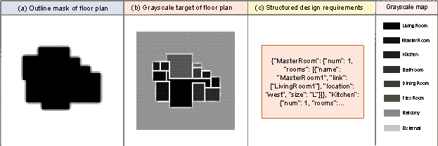
Figure 2 Examples of data for AI-assisted generation of architectural floor plans. (a) Grayscale mask of building outline external contour; (b) Grayscale label diagram of architectural floor plan; (c) Structured room text information
Specifically, the grayscale building outline mask is used to constrain the generation range of the model's predicted noise. The correspondence between each room name and its pixel values in the grayscale target room layout map is listed in Table 1. The structured JSON room text records the room's attributes, including type, quantity, name, connectivity, relative size, and relative position. Connectivity is determined by the presence of a door or an open spatial divider between adjacent rooms. Consistent with Qin et al. (2024), this study classifies room size into five levels (XS, S, M, L, XL) based on the proportion of room area to total building area. The specific corresponding relationship is listed in Table 2. The relative position is divided into nine categories: "west", "east", "north", "south", "center", "southeast", "southwest", "northeast", and "northwest".
Table 1. Correspondence between room types and integer labels
|
Room type |
Label value |
Room type |
Label value |
|
LivingRoom |
0 |
SecondRoom |
7 |
|
MasterRoom |
1 |
Staircase |
8 |
|
Kitchen |
2 |
Balcony |
9 |
|
Bathroom |
3 |
ActivityRoom |
10 |
|
DiningRoom |
4 |
Storage |
11 |
|
FlexRoom |
5 |
OverRoom |
12 |
|
StudyRoom |
6 |
External |
13 |
Table 2 Correspondence between the proportion t of room area to total floor area and size levels
|
Range of t |
Size level |
|
0<t<1/25 |
XS |
|
1/25 |
S |
|
1/16 |
M |
|
1/9 |
L |
|
1/4 |
XL |


Table 3. Complexity comparison between RPLAN and the collected detached-house dataset.
|
Dataset |
Avg. Number |
Num. Range |
Avg. Type |
Avg. Boundary |
Avg. Edges |
|
RPLAN |
6.776 |
[4, 8] |
6.037 |
5.032 |
5.705 |
|
Ours |
9.396 |
[4, 21] |
6.623 |
5.215 |
8.597 |
As shown in Table 3, the collected detached-house dataset exhibits higher layout complexity than RPLAN, with more rooms on average, a wider range of room counts, and denser room adjacency relationships. This suggests that detached house layouts involve more diverse spatial organizations and functional connections, making the target-domain generation task more challenging. Details regarding data availability and access are provided in Appendix A.
In this study, the data were split into training and test sets at a 4:1 ratio. Due to the limited scale of the collected detached house dataset, a floor-level random split was adopted across the three generation stages rather than a building- or project-level split to maintain a balanced distribution of room counts, layout complexity, and floor types. Because no building-level grouping constraint was imposed during the random split, some buildings contributed different floors to both the training and test sets. Since floors within the same building may share geometric and spatial characteristics, such intra-building correlation may lead to optimistic estimates of generalization performance. Accordingly, the reported results should be interpreted as preliminary in-distribution validation on the collected dataset rather than strict project-level generalization. Because different floors of the same building are not jointly modeled, cross-floor consistency requirements, such as vertical column and staircase alignment, are addressed through rule-based post-processing and manual refinement prior to structural modeling and PKPM verification.
3.2 Generation of Floor Plans Based on Transfer Learning and Diffusion Models
Given the limited size of the collected dataset,
a transfer learning strategy was adopted to enhance the model's performance.
In this study, the ChatHouseDiffusion model was first pre-trained on the RPLAN
dataset for 500,000 iterations, with sampling and checkpoint saving performed
every 100,000 steps. The learning rate was set to
 , and the batch size was set to 32. Other
hyperparameters remained consistent with the original study. Subsequently,
the pretrained weights were loaded to initialize the transfer model. All network
parameters were updated during fine-tuning on the self-collected detached
house dataset, without freezing the backbone or using partial layer adaptation.
The model was trained for 10,000 iterations, with generated samples and model
checkpoints saved every 100 iterations, and the learning rate was set to
, and the batch size was set to 32. Other
hyperparameters remained consistent with the original study. Subsequently,
the pretrained weights were loaded to initialize the transfer model. All network
parameters were updated during fine-tuning on the self-collected detached
house dataset, without freezing the backbone or using partial layer adaptation.
The model was trained for 10,000 iterations, with generated samples and model
checkpoints saved every 100 iterations, and the learning rate was set to
 . Meanwhile, to verify the effectiveness
of the transfer learning strategy, a control experiment was conducted by training
the ChatHouseDiffusion model directly from scratch on the custom dataset.
The training settings are illustrated in Appendix C.1 in detail.
. Meanwhile, to verify the effectiveness
of the transfer learning strategy, a control experiment was conducted by training
the ChatHouseDiffusion model directly from scratch on the custom dataset.
The training settings are illustrated in Appendix C.1 in detail.
On the test set, the evaluation metrics for the transfer-learning model peaked at approximately the 7,900th iteration. In the control experiment, the model achieved optimal performance at approximately the 4,800th iteration. The comparative results are presented in Table 4. The generated floor plans are evaluated using pixel-level, room-level, and relation-level metrics, including Micro IoU, Macro IoU, Room Count F1, Room Type F1, and Room Adjacency. These metrics jointly assess spatial similarity, room consistency, and adjacency preservation. Detailed definitions are provided in Appendix B. In Table 4, all values are reported as mean [95% bootstrap confidence interval], with confidence intervals estimated via bootstrap resampling on the test set with 10,000 repetitions.
Table 4 Performance comparison between transfer learning and direct training on the test set. Values are reported as mean [95% bootstrap CI].
|
Metric |
Transfer learning |
Direct training |
|
Micro IoU |
0.6165 [0.5777,0.6555] |
0.1002 [0.0832, 0.1184] |
|
Macro IoU |
0.5223 [0.4810, 0.5645] |
0.0556 [0.0453, 0.0671] |
|
Room Count F1 |
0.6926 [0.6441, 0.7421] |
0.3052 [0.2640, 0.3478] |
|
Room Type F1 |
0.6272 [0.5755, 0.6792] |
0.0681 [0.0435, 0.0747] |
|
Room Adjacency |
0.4970 [0.4317, 0.5650] |
0.1063 [0.0746, 0.1423] |
3.3 Typical Cases of Generated Detached House Floor Plans
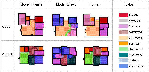
Figure 3 Comparison of results generated by transfer learning and direct training models versus human designs.
Table 5 Metrics for cases generated by Model-Transfer and Model-Direct
|
Case |
Model |
Micro IoU |
Macro IoU |
Room Count F1 |
Room Type F1 |
Room Adjacency |
|
Case 1 |
Model-Transfer |
0.9700 |
0.9772 |
1.000 |
1.000 |
1.000 |
|
Case 1 |
Model-Direct |
0.0540 |
0.0375 |
0.4211 |
0.1053 |
0.2727 |
|
Case 2 |
Model-Transfer |
0.8051 |
0.7881 |
1.000 |
1.000 |
0.9231 |
|
Case 2 |
Model-Direct |
0.2438 |
0.0993 |
0.4211 |
0.000 |
0.1538 |
Owing to the relatively regular room shapes, simple room adjacencies, and moderate number of rooms in Cases 1 and 2, their case-level performance exceeds the overall metrics reported for the test set in Table 4. The generation results from Model-Transfer show a high degree of similarity to the designer's layout. In contrast, Model-Direct produces layouts with lower pixel-level overlap and poor room-level consistency. This indicates that transfer learning significantly improves the model's adherence to constraints during floor plan generation.
4 AI-assisted Generation of Architectural Component Layouts
Following the generation of the floor plan, the subsequent step determines the architectural component layout. Based on the Struct-diffusion framework (Gu et al., 2024), this study develops a task-specific architectural component layout generation module.
4.1 Dataset Construction and Representation
This study employs the binary encoding method from
Struct-diffusion to represent features of room regions and architectural component
positions, constructing a dataset that aligns with the model's input specifications.
Recognizing that architectural component layouts are governed by spatial context
and room typologies, we implement the tensor construction scheme proposed
by Gu et al. (2024). By integrating architectural
layout information, we adapt the Struct-diffusion model—originally developed
for shear wall generation—to the task of generating architectural component
layouts. The formulations of  and
and
 are as follows:
 (5)
(5)
 (6)
(6)
where,  represents the binary tensor for
the exterior walls,
represents the binary tensor for
the exterior walls,  represents the binary tensor for
the windows,
represents the binary tensor for
the windows,  represents the binary tensor for
the internal walls,
represents the binary tensor for
the internal walls,  represents the binary tensor for
the doors and open spatial dividers, and
represents the binary tensor for
the doors and open spatial dividers, and  respectively represent the binary
tensors for the corresponding room types. When a corresponding room type or
architectural component type exists at a certain position, it is marked as
1. Otherwise, it is marked as -1. Figure 4 illustrates an example of
the input and condition tensors.
respectively represent the binary
tensors for the corresponding room types. When a corresponding room type or
architectural component type exists at a certain position, it is marked as
1. Otherwise, it is marked as -1. Figure 4 illustrates an example of
the input and condition tensors.

Figure 4 Input tensor and condition tensor
The potential positions of architectural components are constrained to the boundaries of room polygons. These boundaries serve as the mask for the generative model: positions where a component can validly exist are encoded as 1, while all other positions are set to 0. The mask is formulated as follows:
 (7)
(7)
This study constructs a dataset of architectural
component layouts derived from floor plan drawings of detached houses. The
dataset contains multi-channel binary feature tensors with dimensions of 318
× 18 × 64 × 64, where 318 denotes the total number of floor plan samples,
18 represents the feature channels (with type-to-index mappings detailed in
Table 6), and 64 × 64 indicates the spatial resolution of each feature
map. The feature tensors from four channels—interior walls, exterior walls,
windows, and interior openings (including doors and open spatial dividers)
—are extracted and merged to construct the binary mask tensor
 with a shape of 318 × 1 × 64 ×
64.
with a shape of 318 × 1 × 64 ×
64.
Table 6 Mapping of types to channel indices
|
Type name |
Index value |
Type name |
Index value |
|
LivingRoom |
0 |
Balcony |
9 |
|
MasterRoom |
1 |
ActivityRoom |
10 |
|
Kitchen |
2 |
Storage |
11 |
|
Bathroom |
3 |
OverRoom |
12 |
|
DiningRoom |
4 |
External |
13 |
|
FlexRoom |
5 |
OutWall |
14 |
|
StudyRoom |
6 |
Window |
15 |
|
SecondRoom |
7 |
InWall |
16 |
|
Staircase |
8 |
Door and Split |
17 |
4.2 Generation of Architectural Component Layout Based on Diffusion Models
To examine the contribution of the mask constraint, an additional no-mask ablation setting was introduced. In this setting, the feasible-region mask was removed, while other training settings were kept unchanged. For all settings, an early stopping strategy was employed to reduce overfitting under the limited dataset scale. Specifically, test loss was evaluated at regular intervals, and training was stopped when it did not decrease for 30 consecutive evaluations. A maximum training budget of 20,000 iterations was adopted. The masked model reached optimal performance at iteration 6,799. In contrast, the no-mask model did not satisfy the early stopping criterion within 20,000 iterations. Therefore, the checkpoint with the minimum test loss within the training budget, obtained at iteration 19,599, was used for comparison. The quantitative results of the masked model and the no-mask ablation setting are listed in Table 7. All metric values are also reported as mean [95% bootstrap confidence interval]. Definitions of all evaluation metrics are provided in Appendix B.
Table 7 Ablation study of the mask constraint in architectural component layout generation. Values are reported as mean [95% bootstrap CI].
|
Metric |
With mask |
Without mask |
|
Wall IoU |
0.6716 [0.6422, 0.7018] |
0.6355 [0.6007, 0.6710] |
|
Door IoU |
0.4761 [0.4298, 0.5249] |
0.4586 [0.4091, 0.5112] |
|
Window IoU |
0.5444 [0.4903, 0.5969] |
0.5432 [0.4903, 0.5948] |
|
Macro IoU |
0.5640 [0.5265, 0.6025] |
0.5458 [0.5063, 0.5866] |
|
Micro IoU |
0.7479 [0.7222, 0.7733] |
0.7114 [0.6806, 0.7418] |
|
Connectivity F1 |
0.6290 [0.5528, 0.7035] |
0.6011 [0.5385, 0.6610] |
|
Selected iteration |
6799 |
19599 |
|
Training status |
Early-stopped |
Not early stopped |
As shown in Table 7, the masked model outperforms the no-mask setting across all metrics. The improvement is most evident in Micro IoU, which increases from 0.7114 to 0.7479, indicating better overall spatial consistency. Improvements are also observed in Wall IoU, Door IoU, Macro IoU, and Connectivity F1, while Window IoU remains nearly unchanged. These results suggest that the mask constraint provides useful geometric guidance for architectural component placement. Although the no-mask model still achieves competitive results, it requires substantially more training iterations and does not reach the early stopping criterion within the maximum training budget. Therefore, considering both generation accuracy and convergence efficiency, the masked setting is adopted as the final configuration.
4.3 Case Study of Architectural Component Layout
Figure 5 displays selected generation results sampled from the optimal model on the test set, along with the human-designed results. The corresponding evaluation metrics for each case are listed in Table 8. Additional qualitative comparisons between generated architectural component layouts and the corresponding ground-truth designs are provided in Appendix Figure D.2.
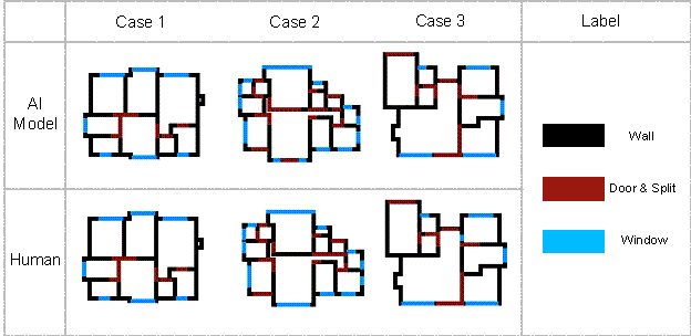
Figure 5 Generated architectural component layout results compared with human design
Table 8 Evaluation metrics of each case in the architectural component layout generation task
|
Metric |
Case 1 |
Case 2 |
Case 3 |
|
Wall IoU |
1.0000 |
0.8983 |
0.9887 |
|
Door IoU |
1.0000 |
0.7051 |
0.9344 |
|
Window IoU |
1.0000 |
0.9028 |
0.9535 |
|
Micro-IoU |
1.0000 |
0.9208 |
0.9856 |
|
Macro-IoU |
1.0000 |
0.8354 |
0.9663 |
|
Connectivity F1 |
1.0000 |
1.0000 |
1.0000 |
The generated layout exhibits high similarity and consistency in connectivity with the overall layout designed by the designer, with only a few architectural components differing in position from the manually designed scheme. This indicates that the model can accurately extract the underlying spatial constraints between room layouts and architectural component layouts. However, differences remain in the generation of fine-grained components such as doors and windows. For example, in Case 2, the main local error is that the model generates a front door at a position corresponding to a window in the reference design. This may be attributed to the current floor-level dataset generation setting, where the component layout is not explicitly coupled to the first-floor entrance arrangement. This type of error can be corrected in the subsequent cross-floor alignment process using rule-based adjustment or manual refinement.
5 AI-assisted Design of Columns and Beams in Frame Structures
Frame structures are widely adopted for multi-story detached houses. Based on the Struct-diffusion model, the rule-based masked diffusion model for beam layouts (Liao et al., 2025), and the Heterogeneous Graph Neural Network (HGNN) for member sizing (Qin et al., 2025), this study proposes a sequential three-stage design workflow. The workflow comprises: (1) AI-assisted column layout generation utilizing the Struct-diffusion model; (2) rule-based beam layout design that accounts for load transfer mechanisms and global structural topology; and (3) AI-assisted member section sizing for beams and columns based on the HGNN model. In the first stage, a binary feature tensor dataset for frame columns is constructed, and the input and conditional tensor formulations are adapted to enable AI-assisted column layout generation via the Struct-diffusion model. In the second and third stages, the beam layout and intelligent sizing modules integrated into AI-Structure Copilot (Qin, Liao, et al., 2024) are employed directly. Finally, the design results are modeled in PKPM to calculate mechanical performance metrics and verify compliance with relevant codes.
5.1 Dataset Construction and Representation
57 sets of structural design drawings were collected in this study, which were then systematically preprocessed. Relevant entity information was extracted from the preprocessed drawings, yielding a binary feature tensor with the shape of 57 × 19 × 64 × 64, where 57 denotes the total number of data samples, 19 represents the number of feature channels, and 64 × 64 specifies the pixel resolution of each channel. Among the 19 feature channels, the first 18 channels correspond to individual room types or architectural component types, with the same correspondence presented in Table 6, while the 19th channel encodes the binary features of frame column locations.
Although frame column positions are typically represented by their centroids, directly encoding each centroid as a single pixel in a feature map leads to highly sparse supervision, which may hinder model convergence and reduce generation accuracy. To alleviate this issue, a column center pixel expansion strategy is adopted. As illustrated in Figure 6, column centers are first extracted from the original DXF plan and then expanded into local pixel patterns according to the directions of the connected architectural components. This expanded representation increases the spatial density of column labels while preserving the original column center locations.
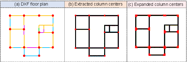
Figure 6. Illustration of the column center extraction and pixel expansion strategy. (a) Original DXF plan with column centers; (b) extracted column center representation; (c) expanded column centers used for model training.
5.2 AI-assisted Generation of Frame Columns Layout Based on Diffusion Models
The generation of frame
column layouts is analogous to the generation of shear wall component layouts.
According to the feature representation method of input tensors and condition
tensors in the research of Gu et al.,  in this stage is defined as follows:
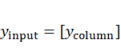 (8)
(8)
where,  represents the binary tensor of the channel corresponding
to frame columns. Given that column placement is inherently constrained by
the floor plan and architectural component layouts, the binary tensors for
the rooms and architectural components are concatenated to form the condition
tensor that guides generation. The formulation of the condition tensor is
defined as follows:
represents the binary tensor of the channel corresponding
to frame columns. Given that column placement is inherently constrained by
the floor plan and architectural component layouts, the binary tensors for
the rooms and architectural components are concatenated to form the condition
tensor that guides generation. The formulation of the condition tensor is
defined as follows:
 (9)
(9)
where,  ,
,  , … represent the binary tensors of each
room respectively, while
, … represent the binary tensors of each
room respectively, while  , … represent the binary tensors of each
architectural component respectively, which are consistent with those in formulation
(5) and formulation (6). Additionally,
, … represent the binary tensors of each
architectural component respectively, which are consistent with those in formulation
(5) and formulation (6). Additionally,  denotes the concatenation of the
binary feature tensors along the channel dimension.
denotes the concatenation of the
binary feature tensors along the channel dimension.
Frame columns are usually arranged on the axes overlapping with architectural component layouts. Therefore, the union of the positions of architectural components is taken as the mask. The formula of the mask tensor is defined as follows:
 (10)
(10)
where,  denotes the union operation of
all selected binary feature tensors.
denotes the union operation of
all selected binary feature tensors.
To further examine the contributions of the architectural component constraints obtained from the upstream model and the column-center pixel expansion strategy, two ablation settings were introduced in addition to the proposed model. In the first setting, the architectural-component constraint channels were removed from the condition tensor to evaluate the effect of upstream architectural-component information on frame-column placement. In the second setting, the column centers were represented using single-centroid pixels without pixel expansion, while the remaining input conditions were left unchanged. All models were trained and evaluated using the same data split, early stopping strategy, and evaluation protocol to ensure a fair comparison.
The ratio of the training set to the test set is 4:1. Similar to the architectural component generation model, the optimal checkpoint was selected according to the minimum test loss under the same early stopping strategy as the training of the architectural component layout generation model. In this task, the input tensor has 1 channel, and the condition tensor has 18 channels; therefore, the number of input channels is defined as 19 (1 + 18), and the number of output channels is 1. The definition of other hyperparameters is the same as that in Section 4.2, which are illustrated in Appendix C.3 in detail. Since there is only one label type (frame columns), Micro IoU and Macro IoU have the same calculated value, i.e., IoU (Everingham et al., 2010). Therefore, IoU is used as the evaluation metric for frame column layout generation. Table 9 reports the mean IoU, 95% bootstrap confidence interval, and standard deviation.
Table 9. Ablation study of the frame column placement model. Values are reported as mean IoU [95% bootstrap CI] and standard deviation.
|
Method |
Selected iteration |
IoU [95% CI] |
Standard deviation |
|
w/o architectural component constraints |
1399 |
0.7079 [0.6244, 0.8033] |
0.1507 |
|
w/o expansion |
12599 |
0.7615 [0.6375, 0.8767] |
0.2051 |
|
Proposed |
9399 |
0.7885 [0.6930, 0.8775] |
0.1576 |

Additional qualitative comparisons between generated column placement results and the corresponding ground-truth designs are provided in Appendix Figure D.3.
5.3 AI-assisted Design of Frame Beams and Member Section Sizing
After generating the frame columns, this study employs the AI-assisted beam layout and member section sizing modules integrated in AI-Structure Copilot to complete the structural design (Qin, Liao, et al., 2024). To evaluate the structural performance, a PKPM analysis model is automatically constructed from the generated design data.
For the member section sizing, a generative design method based on heterogeneous graph neural networks (HetGNN) (Qin et al., 2025) is adopted. By representing beams, columns, and slabs as a heterogeneous graph, the model effectively captures complex topological dependencies. The HetGNN can generate sections within seconds, with an average deviation from manual designs of only 50 mm (equivalent to a standard dimension increment).
6 Case Study of the AI-Assisted Sequential Architectural and Structural Design Workflow
6.1 Project Information of the Case
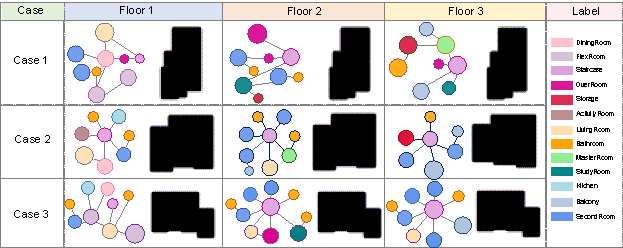
Figure 7 Bubble diagrams and outline masks for each case
6.2 AI-Assisted Architectural and Structural Design Results
The design requirements are organized in JSON format and fed into the trained floor plan generation model, along with masks, for predictive generation. The initial model results are shown in Figure 8, with an average generation time of approximately 40 seconds for each case.
Since the raw generated layouts may still contain local geometric inaccuracies and minor deviations from practical design constraints, manual refinement was performed in CAD before the subsequent structural design stages. The refinement mainly involved boundary correction, room-type adjustment, and cross-floor coordination. The refined floor plans are also presented in Figure 8, and the manual refinement required approximately 16 min for each case.
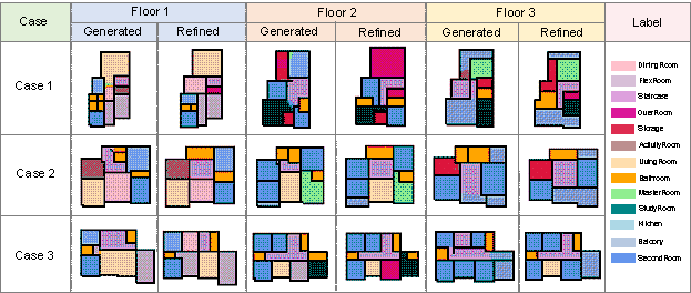
Figure 8 Generated and refined results of floor plans of each case
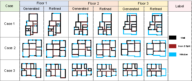
Figure 9 Generation and refined results of architectural component layouts of each case
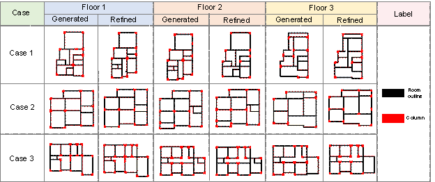
Figure 10 Generated and refined results of column placement of each case
Based on the above design results, a rule-based masked diffusion model is employed to automatically generate layouts for frame beams, and a Heterogeneous Graph Neural Network (HetGNN) model is then used to predict the section dimensions of both beams and columns. Case 1 is designed under seismic conditions of Intensity 7 (i.e., the design basic peak ground acceleration (PGA) is 0.10 g, representing the seismic hazard level with a 10% probability of exceedance in 50 years), and the site characteristic period is 0.35 s. Case 2 is also designed under the seismic conditions of Intensity 7, with a design basic PGA of 0.10 g. The site class is Class II, and the design earthquake group is Group 1, corresponding to a site characteristic period of 0.35 s. Case 3 is designed for seismic conditions at Intensity 7, with a design basic PGA of 0.15 g. The site class is Class II, and the design earthquake group is Group 2, corresponding to a site characteristic period of 0.40 s. The component dimensions and concrete strength grades assigned to each case are detailed in Appendix E, respectively. Taking the first-floor planes of each case as examples, the results are shown in Figure 11. The beam layout is completed in approximately 2 minutes, followed by member section sizing, which takes about 2 minutes per case.
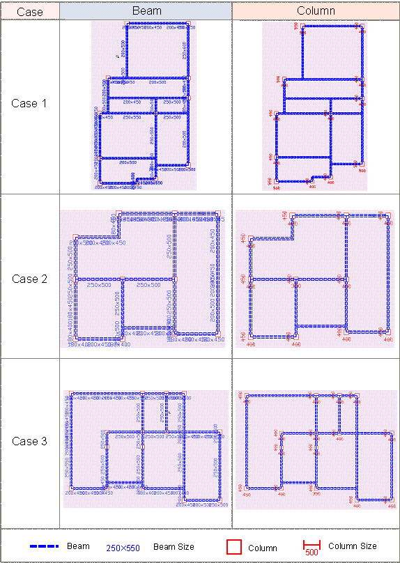
Figure 11 Frame beam layouts and beam and column section dimensions of the first floor of each case (mm)
Based on the final design, three structural models of the cases are developed and analyzed using the PKPM software suite to validate their mechanical performance. This entire modeling and verification process is completed in approximately 2 minutes. The resulting key mechanical performance metrics are summarized in Table 10.
Table 10 Mechanical performance metrics of the design results of the three cases
|
Metric |
Case 1 |
Case 2 |
Case 3 |
Code limit |
|
Mass ratio |
1.0509 |
1.2103 |
1.0254 |
=<1.5 |
|
Structural natural vibration period (s) - X |
0.533 |
0.4218 |
0.4014 |
/ |
|
Structural natural vibration period (s) - Y |
0.4882 |
0.4146 |
0.4148 |
/ |
|
Structural natural vibration period (s) - T |
0.4264 |
0.3191 |
0.3497 |
/ |
|
Period ratio |
0.8 |
0.7566 |
0.8431 |
<=0.9 |
|
Minimum shear-weight ratio - X |
0.0517 |
0.0676 |
0.1046 |
>=1.6% |
|
Minimum shear-weight ratio - Y |
0.0525 |
0.0548 |
0.0872 |
>=1.6% |
|
Stiffness-weight ratio - X |
14.5228 |
90.5754 |
102.0172 |
>=10 |
|
Stiffness-weight ratio - Y |
17.8539 |
89.9464 |
100.034 |
>=10 |
|
Maximum inter-story drift ratio (earthquake) - X |
1 / 1368 |
1 / 1968 |
1 / 1214 |
=<1/550 |
|
Maximum inter-story drift ratio (earthquake) - Y |
1 / 1528 |
1 / 1704 |
1 / 1178 |
=<1/550 |
|
Maximum displacement ratio - X |
1.2198 |
1.0771 |
1.1014 |
<=1.50 |
|
Maximum displacement ratio - Y |
1.1364 |
1.3642 |
1.3938 |
<=1.50 |
|
Maximum story drift ratio - X |
1.459 |
1.0913 |
1.1297 |
<=1.50 |
|
Maximum story drift ratio - Y |
1.4015 |
1.4102 |
1.4315 |
<=1.50 |
Using the proposed workflow, generating a comprehensive preliminary design—comprising both the floor plan and the frame structure—takes approximately 39 minutes for each case. This process includes AI-based generation and manual interactive refinement. To quantify the efficiency improvement, a comparative study was conducted between the proposed AI-assisted design workflow and the conventional manual design process. For the manual baseline, the recorded time started from reading the design requirements and the building outline CAD drawing, and ended when the preliminary architectural plan, architectural component layout, structural layout, and structural verification were completed. For the AI-assisted workflow, the recorded time started from the preparation and input of the structured design requirements and ended after model inference, result checking, necessary manual refinement, and structural verification were completed. Six engineers participated in the manual baseline, with 4-17 years of professional experience and an average of 9.5 years.
The average time consumption results are summarized in Table 11.
Table 11 Average time consumption of each stage of the AI-assisted design workflow and the manual design process
|
Design stage |
AI-assisted design |
Manual design |
|
16 min |
170 min |
|
|
Door and window layout |
9 min |
39 min |
|
Frame column layout |
8 min |
31 min |
|
Frame beam layout |
3 min |
35 min |
|
Preliminary section sizing and analysis |
3 min |
90 min |
|
Performance indicator refinement |
/ |
51 min |
|
Structural drawing generation |
/ |
21 min |
|
Total time expenditure |
39 min |
437 min |
The case-level time comparison shows that the AI-assisted workflow can substantially reduce the time required for preliminary detached house design. As summarized in Table 11, the AI-assisted workflow completes the core design tasks in 39 min, whereas the conventional manual workflow requires 437 min, corresponding to an approximately 91% reduction in design time. The time reduction is mainly observed in repetitive stages such as architectural space partitioning, architectural component layout generation, and member section sizing. In addition, automatic checking and drawing generation reduce the need for separate manual refinement and documentation operations. Nevertheless, human refinement remains necessary for coordinating design details, interpreting subjective user requirements, and ensuring engineering usability. Therefore, the results should be interpreted as case-level evidence of the efficiency potential of the proposed AI-assisted workflow rather than a general estimate of productivity improvement. The magnitude of the measured efficiency gain may vary with engineer expertise and project characteristics, and further evaluation involving more projects, participants, and repeated experiments is required for a more comprehensive assessment.
Overall, the selected cases indicate the potential efficiency benefits of the proposed workflow in preliminary detached house design, particularly for repetitive tasks such as floor plan design, architectural component layout design, column layout design, and structural member sizing. At the same time, the results should be interpreted as evidence for the feasibility of using the proposed workflow as an AI-assisted tool within the professional design process, rather than as a fully automated substitute for architects and structural engineers.
7 Discussion
7.1 Limitations
(1) Dataset scale and generalization. The proposed workflow is developed and evaluated on a self-collected dataset of Chinese detached house construction drawings. Although the dataset provides real-world engineering data, its scale remains limited compared with large public residential datasets. To maintain a balanced distribution of room quantities, functional categories, and layout complexity, a floor-level train-test split was adopted rather than project-level partitioning or cross-validation. Therefore, the reported results should be interpreted as preliminary in-distribution validation, and further evaluation on larger and more diverse datasets is required to assess project-level generalization.
(2) Limited modeling of architectural design constraints. The current workflow mainly relies on data-driven learning and does not explicitly model higher-level architectural objectives, such as circulation quality, functional zoning, daylighting and ventilation, and detailed code compliance. Although the generated layouts generally follow patterns learned from the training data, these design criteria are not directly optimized or automatically evaluated. Professional assessments from architects and end users also remain to be further incorporated.
(5) Representation resolution and structural scope. To improve computational efficiency, the diffusion models operate on 64 × 64 representations, which may limit the generation of fine geometric details. In addition, the current workflow focuses on preliminary structural design, including column and beam layout generation, member section sizing, and PKPM-based code verification. More detailed tasks, such as slab design, reinforcement detailing, and foundation design, remain beyond the scope of this study. Moreover, the current structural verification is conducted only under Chinese seismic design provisions. Since structural design requirements and code provisions vary across countries and regions, further validation and adaptation under other national design standards are required before broader international engineering applicability can be established.
7.2 Future Work
Future research can focus on expanding the scale and diversity of datasets, improving the modeling of architectural knowledge and design constraints, and introducing architecture and structure collaborative feedback mechanisms. In addition, it is also necessary to further investigate unified cross-stage information representations and more powerful generative architectures to enable smoother information transfer throughout the workflow and reduce reliance on manual refinement and rule-based post-processing. Establishing explicit multi-floor consistency constraints and incorporating higher-resolution representations are also expected to further improve design quality. Moreover, future work should combine automatic metrics with expert review and user-based evaluation to provide a more comprehensive assessment of the generated design results. Finally, extending the workflow to more comprehensive structural design tasks and adapting it to different building types and design codes will broaden its application scope.
8 Conclusion
This study developed a diffusion-based sequential generative workflow for AI-assisted architectural and structural design of detached houses. A Chinese detached house architectural and structural dataset is collected and constructed from real engineering drawings, providing a domain-specific data foundation for preliminary validation.
The proposed workflow connects floor plan generation, architectural component layout generation, frame column layout generation, beam layout generation, member section sizing, and PKPM-based verification. For floor plan generation, the model was pretrained on RPLAN dataset and fully fine-tuned on the self-collected detached house dataset. The comparison with direct training shows that full-parameter transfer learning can effectively improve generation performance under limited data, with Micro IoU and Macro IoU reaching 0.6165 and 0.5223, respectively. In the subsequent stages, binary feature tensors were used to represent conditions for architectural component layout generation and column layout generation. The architectural component layout generation and column layout generation models achieve a Micro IoU of 0.7479 and an IoU of 0.7885, respectively, indicating that results generated by upstream models can be progressively incorporated into downstream modules.
The case study further demonstrates that the manually refined AI-assisted results can be connected to existing beam layout generation, member section sizing, and PKPM-based verification methods under the investigated design condition. The case-level timing comparison also indicates the potential of the proposed workflow to improve preliminary design efficiency.
Overall, the experimental results demonstrate the potential engineering application value of the proposed workflow. Nevertheless, this study still has several limitations, including the limited dataset scale, the lack of explicit cross-floor coupled modeling, the absence of high-rise architectural constraints, the limited scope of case-based verification, and the remaining reliance on manual refinement. Future work will further expand the dataset, incorporate stronger multi-floor and architectural constraints, reduce manual intervention, and broaden the applicability of the proposed workflow to more diverse building types and design scenarios.
Acknowledgments
This work was supported by the Research Project of China Civil Engineering Society (ZC202511260107), National Natural Science Foundation of China (52408348), Beijing Municipal Natural Science Foundation (8252008), Sichuan Science and Technology Program (2025ZNSFSC1312), Fundamental Research Funds for the Central Universities (2682025CX041), and Tsinghua University Initiative Scientific Research Program (2025Z03KYY001).
References
Benros, D., Duarte, J.P., Hanna, S., 2009. An integrated system for providing mass customized housing. Automation in Construction 18(3), 310–320. doi:10.1016/j.autcon.2008.09.006.
Castro Pena, M.L., Carballal, A., Rodríguez-Fernández, N., Santos, I., Romero, J., 2021. Artificial intelligence applied to conceptual design. A review of its use in architecture. Automation in Construction 124, 103550. doi:10.1016/j.autcon.2021.103550.
Chang, K.-H., Cheng, C.-Y., Luo, J., Murata, S., Nourbakhsh, M., Tsuji, Y., 2021. Building-GAN: Graph-conditioned architectural volumetric design generation. In: Proceedings of the IEEE/CVF International Conference on Computer Vision (ICCV), pp. 11936–11945. doi:10.1109/ICCV48922.2021.01174.
Dhariwal, P., Nichol, A., 2021. Diffusion models beat GANs on image synthesis. Advances in Neural Information Processing Systems 34, 8780–8794.
Fei, Y., Liao, W., Zhang, S., Yin, P., Han, B., Zhao, P., Chen, X., Lu, X., 2022. Integrated schematic design method for shear wall structures: A practical application of generative adversarial networks. Buildings 12(9), 1295. doi: 10.3390/buildings12091295.
Gu, Y., Huang, Y., Liao, W., Lu, X., 2024. Intelligent design of shear wall layout based on diffusion models. Computer-Aided Civil and Infrastructure Engineering 39(23), 3610–3625. doi:10.1111/mice.13236.
He, Z., Wang, Y.-H., Zhang, J., 2025. Generative AIBIM: An automatic and intelligent structural design pipeline integrating BIM and generative AI. Information Fusion 114, 102654. doi:10.1016/j.inffus.2024.102654.
Ho, J., Jain, A., Abbeel, P., 2020. Denoising diffusion probabilistic models. Advances in Neural Information Processing Systems 33, 6840–6851.
Ho, J., Salimans, T., 2022. Classifier-free diffusion guidance. arXiv:2207.12598. doi:10.48550/arXiv.2207.12598.
Hu, R., Huang, Z., Tang, Y., van Kaick, O., Zhang, H., Huang, H., 2020. Graph2Plan: Learning floorplan generation from layout graphs. ACM Transactions on Graphics 39(4), Article 118. doi:10.1145/3386569.3392391.
Kim, I., Shin, J., Shah, S.H., Rehman, S.U., 2024. Client-centered detached modular housing: natural language processing-enabled design recommender system. Journal of Computational Design and Engineering 11(3), 137–157. doi:10.1093/jcde/qwae041
Larsen, M.S.S., Lindhard, S.M., Brunø, T.D., Nielsen, K., Larsen, J.K., 2019. Mass customization in the house building industry: Literature review and research directions. Frontiers in Built Environment 5, 115. doi:10.3389/fbuil.2019.00115.
Leng, S., Zhou, Y., Dupty, M.H., Lee, W.S., Joyce, S.C., Lu, W., 2023. Tell2Design: A dataset for language-guided floor plan generation. In: Proceedings of the 61st Annual Meeting of the Association for Computational Linguistics (Volume 1: Long Papers), pp. 14680–14697. doi:10.18653/v1/2023.acl-long.820.
Liao, W., Lu, X., Huang, Y., Zheng, Z., Lin, Y., 2021. Automated structural design of shear wall residential buildings using generative adversarial networks. Automation in Construction 132, 103931. doi:10.1016/j.autcon.2021.103931.
Liao, W., Xia, J., Gu, Y., Lu, X., 2025. Intelligent beam layout design for shear wall structures based on diffusion model constrained by rule-generated mask. Manuscript submitted for publication.
Liu, J., Xue, Y., Duarte, J.P., Shekhawat, K., Zhou, Z., Huang, X., 2022. End-to-end graph-constrained vectorized floorplan generation with panoptic refinement. In: Computer Vision – ECCV 2022, Lecture Notes in Computer Science, vol. 13675, pp. 547–562. doi:10.1007/978-3-031-19784-0_32.
Lopes, R., Tutenel, T., Smelik, R.M., de Kraker, K.J., Bidarra, R., 2010. A constrained growth method for procedural floor plan generation. In: Proceedings of GAME-ON 2010, Leicester, United Kingdom.
Málaga-Chuquitaype, C., 2022. Machine learning in structural design: An opinionated review. Frontiers in Built Environment 8, 815717. doi:10.3389/fbuil.2022.815717.
Merrell, P., Schkufza, E., Koltun, V., 2010. Computer-generated residential building layouts. ACM Transactions on Graphics 29(6), Article 181. doi:10.1145/1866158.1866203.
Mohamed, B.E., Abd Elrahman, A.S., Nassar, K., 2022. Mass customization of housing: A framework for integrating user preferences into housing design. Buildings 12(7), 955. doi:10.3390/buildings12070955.
Mostafavi, F., van Engelenburg, C., Khademi, S., Vrachliotis, G., 2024. Floor plan generation: The interplay among data, machine, and designer. International Journal of Architectural Computing 23(2), 370–386. doi:10.1177/14780771241290649.
Mou, C., Wang, X., Xie, L., Wu, Y., Zhang, J., Qi, Z., Shan, Y., Qie, X., 2024. T2I-Adapter: Learning adapters to dig out more controllable ability for text-to-image diffusion models. Proceedings of the AAAI Conference on Artificial Intelligence 38(5), 4296–4304. doi:10.1609/aaai.v38i5.28226.
Nauata, N., Chang, K.-H., Cheng, C.-Y., Mori, G., Furukawa, Y., 2020. House-GAN: Relational generative adversarial networks for graph-constrained house layout generation. In: Computer Vision – ECCV 2020, Lecture Notes in Computer Science, pp. 162–177. doi:10.1007/978-3-030-58452-8_10.
Nauata, N., Hosseini, S., Chang, K.-H., Chu, H., Cheng, C.-Y., Furukawa, Y., 2021. House-GAN++: Generative adversarial layout refinement network towards intelligent computational agent for professional architects. In: Proceedings of the IEEE/CVF Conference on Computer Vision and Pattern Recognition (CVPR), pp. 13627–13636. doi:10.1109/CVPR46437.2021.01342.
Newton, D., 2019. Generative deep learning in architectural design. Technology|Architecture + Design 3(2), 176–189. doi:10.1080/24751448.2019.1640536.
Nyokum, T., et al., 2025. Artificial intelligence in civil engineering: Emerging innovations, applications and future directions. Frontiers in Built Environment 11, 1622873. doi:10.3389/fbuil.2025.1622873.
Pan, S.J., Yang, Q., 2010. A survey on transfer learning. IEEE Transactions on Knowledge and Data Engineering 22(10), 1345–1359. doi:10.1109/TKDE.2009.191.
Qin, S., He, C., Chen, Q., Yang, S., Liao, W., Gu, Y., Lu, X., 2024. ChatHouseDiffusion: Prompt-guided generation and editing of floor plans. arXiv:2410.11908. doi:10.48550/arXiv.2410.11908.
Qin, S., Liao, W., Huang, S., Hu, K., Tan, Z., Gao, Y., Lu, X., 2024. AIstructure-Copilot: Assistant for generative AI-driven intelligent design of building structures. Smart Construction 2024(1), 0001. doi:10.55092/sc20240001.
Qin, S., Liao, W., Huang, Y., Zhang, S., Gu, Y., Han, J., Lu, X., 2025. Intelligent design for component size generation in reinforced concrete frame structures using heterogeneous graph neural networks. Automation in Construction 171, 105967. doi:10.1016/j.autcon.2025.105967.
Rodrigues, E., Gaspar, A.R., Gomes, A., 2013. An evolutionary strategy enhanced with a local search technique for the space allocation problem in architecture, Part 1: Methodology. Computer-Aided Design 45(5), 887–897. doi:10.1016/j.cad.2013.01.001.
Rombach, R., Blattmann, A., Lorenz, D., Esser, P., Ommer, B., 2022. High-resolution image synthesis with latent diffusion models. In: Proceedings of the IEEE/CVF Conference on Computer Vision and Pattern Recognition (CVPR), pp. 10674–10685. doi:10.1109/CVPR52688.2022.01042.
Shabani, M.A., Hosseini, S., Furukawa, Y., 2023. HouseDiffusion: Vector floorplan generation via a diffusion model with discrete and continuous denoising. In: Proceedings of the IEEE/CVF Conference on Computer Vision and Pattern Recognition (CVPR), pp. 5466–5475. doi:10.1109/CVPR52729.2023.00529.
Sherif, M., Nassar, K., Hosny, O., Safar, S., Abotaleb, I., 2022. Automated BIM-based structural design and cost optimization model for reinforced concrete buildings. Scientific Reports 12, 21616. doi:10.1038/s41598-022-26146-6.
Song, J., Meng, C., Ermon, S., 2021. Denoising diffusion implicit models. In: International Conference on Learning Representations (ICLR). arXiv:2010.02502. doi:10.48550/arXiv.2010.02502.
Song, Y., Sohl-Dickstein, J., Kingma, D.P., Kumar, A., Ermon, S., Poole, B., 2021. Score-based generative modeling through stochastic differential equations. In: International Conference on Learning Representations (ICLR). arXiv:2011.13456. doi:10.48550/arXiv.2011.13456.
Takeuchi, Y., An, Q., Yamashita, A., 2024. Boundary conditioned floor layout generation with diffusion model. In: SIGGRAPH Asia 2024 Posters, Article 48, pp. 1–2. doi:10.1145/3681756.3697884.
Wu, W., Fu, X.-M., Tang, R., Wang, Y., Qi, Y.-H., Liu, L., 2019. Data-driven interior plan generation for residential buildings. ACM Transactions on Graphics 38(6), Article 234, 1–12. doi:10.1145/3355089.3356556.
Zhang, L., Rao, A., Agrawala, M., 2023. Adding conditional control to text-to-image diffusion models. In: Proceedings of the IEEE/CVF International Conference on Computer Vision (ICCV), pp. 3813–3824. doi:10.1109/ICCV51070.2023.00355.
Zhao, P., Liao, W., Huang, Y., Lu, X., 2023. Intelligent design of shear wall layout based on attention-enhanced generative adversarial network. Engineering Structures 274, 115170. doi:10.1016/j.engstruct.2022.115170.
Zhou, Y., Leng, H., Meng, S., Wu, H., Zhang, Z., 2024. StructDiffusion: End-to-end intelligent shear wall structure layout generation and analysis using diffusion model. Engineering Structures 309, 118068. doi:10.1016/j.engstruct.2024.118068.
Zhuang, F., Qi, Z., Duan, K., Xi, D., Zhu, Y., Zhu, H., Xiong, H., He, Q., 2020. A comprehensive survey on transfer learning. Proceedings of the IEEE 109(1), 43–76. doi:10.1109/JPROC.2020.3004555.
Appendix A. Dataset Description and Open Access
A.1 Dataset description
In addition to the architectural layout data, 57 detached house projects containing complete frame structural design information are further selected for column layout tasks. Therefore, the dataset used in this study contains both architectural design data for floor plan and architectural component layout generation, and a smaller subset with structural information for column layout generation.
A.2 Dataset availability
The processed dataset is made available through the following GitHub repository. The floor plan data are released in PNG format, whereas the architectural component layout and frame column layout data are released as multi-channel MAT files consistent with the representations used in this study. The original DXF files cannot be released due to data ownership constraints.
The dataset is available at: https://github.com/Iceberg-cloud/Chinese-detached-house-dataset
Appendix B. Definitions of Evaluation Metrics
B.1 Pixel-level similarity metrics
(1) IoU:
 (B-1)
(B-1)
where  denotes the predicted pixels of class c, and
  denotes the ground-truth
pixels of class c.
denotes the ground-truth
pixels of class c.
(2) Micro IoU:
 (B-2)
(B-2)
where C is the number of semantic classes.
(3) Macro IoU:
 (B-3)
(B-3)
B.2 Room-level architectural metrics
(1) Room Count F1 evaluates whether the generated layout correctly predicts the number of rooms at matched spatial locations. It is calculated as:
 (B-4)
(B-4)
where  and
and  denote the precision and recall of the number of correctly
matched room instances.
denote the precision and recall of the number of correctly
matched room instances.
(2) Room Type F1 evaluates whether the generated layout correctly predicts the functional types of matched rooms:
 (B-5)
(B-5)
where  and
and  denote the precision and recall of correctly classified
room types.
denote the precision and recall of correctly classified
room types.
(3) Room Adjacency Accuracy measures the proportion of correctly predicted adjacency relationships between rooms:
 (B-6)
(B-6)
where  is the number of room adjacency relationships correctly
predicted by the model, and
is the number of room adjacency relationships correctly
predicted by the model, and  is the number of adjacency relationships in the ground-truth
design.
is the number of adjacency relationships in the ground-truth
design.
B.3 Component connectivity metrics
(1) Connectivity F1 evaluates whether doors correctly establish functional connections between room pairs:
 (B-7)
(B-7)
where  and
and  represent the precision and recall of correctly generated
door-based room connections.
represent the precision and recall of correctly generated
door-based room connections.
Appendix C. Model Training Hyperparameters
C.1 Floor plan generation
Table C.1 Hyperparameter settings of the floor plan generation model
|
Parameter |
Setting |
|
Backbone model |
ChatHouseDiffusion |
|
Source-domain dataset |
RPLAN |
|
Target-domain dataset |
Self-collected Chinese detached house dataset |
|
Image resolution |
64 × 64 |
|
Learning rate |
|
|
Batch size |
32 |
|
Pretraining iterations |
500,000 |
|
Fine-tuning iterations |
Early stopping (max. 500,000 iterations) |
|
Sampling interval |
100 steps |
|
Optimizer |
Adam, |
|
Diffusion steps |
1000 |
|
Noise schedule |
Sigmoid |


C.2 Architectural component layout generation
Table C.2 Hyperparameter settings of the architectural component layout generation model
|
Parameter |
Setting |
|
Backbone model |
Struct-diffusion |
|
Dataset |
Self-collected Chinese detached house dataset |
|
Image resolution |
64 × 64 |
|
Learning rate |
|
|
Batch size |
8 |
|
Training iterations |
Early stopping (max. 20,000 iterations) |
|
Sampling interval |
125 steps |
|
Optimizer |
Adam, |
|
Diffusion steps |
2000 |
|
Noise schedule |
Linear |



C.3 Column placement generation
Table C.3 Hyperparameter settings of the column placement model
|
Parameter |
Setting |
|
Backbone model |
Struct-diffusion |
|
Dataset |
Self-collected Chinese detached house dataset |
|
Image resolution |
64 × 64 |
|
Learning rate |
|
|
Batch size |
8 |
|
Training iterations |
Early stopping (max. 20,000 iterations) |
|
Sampling interval |
125 steps |
|
Optimizer |
Adam, |
|
Diffusion steps |
2000 |
|
Noise schedule |
Linear |



C.4 Discussion of inherited hyperparameters
This adjustment is made to reduce overtraining and unnecessary computational cost under limited data. A systematic hyperparameter search is not conducted because this study focuses on validating the sequential architectural and structural workflow, and the major hyperparameters has already been validated in the original studies. Therefore, the original hyperparameter settings were used as the basis, while early stopping was adopted to select suitable checkpoints for the target dataset. Because no systematic hyperparameter optimization was performed, the reported results should be interpreted as the performance obtained under the inherited and moderately adjusted settings, rather than the optimal achievable performance of the adopted models. Systematic hyperparameter optimization will be investigated in future work with larger detached-house datasets.
Appendix D. Supplementary Test Results
D.1 Floor plan generation results
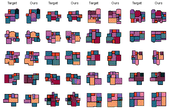
Figure D.1 Representative floor plan generation results.
D.2 Architectural component layout generation results
Similarly, 20 representative architectural component layout generation cases are selected to visualize the model behavior under different design conditions and complexity levels, as shown in Figure D.2. The results illustrate the model's ability to generate walls, doors, windows, and open spatial dividers across diverse floor plan layouts.
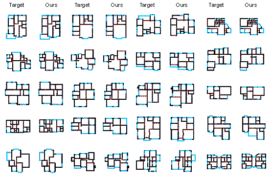
Figure D.2 Representative architectural component layout generation results.
D.3 Column layout generation results
For the frame column layout generation task, 8 representative test cases are selected for supplementary visualization, as shown in Figure D.3. The number of displayed cases is smaller than that of the above tasks because the available dataset with complete frame structural design information is more limited.
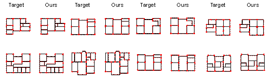
Figure D.3 Representative column layout results
Appendix E. Input Conditions for Case Studies
E.1 JSON Inputs of Each Case
This section provides the JSON inputs of the three cases tested in the study.
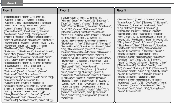
Figure E.1 JSON inputs of Case 1
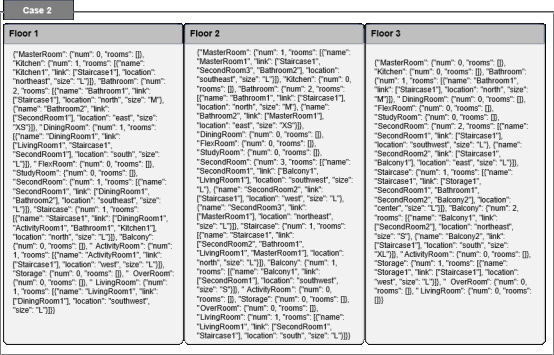
Figure E.2 JSON inputs of Case 2
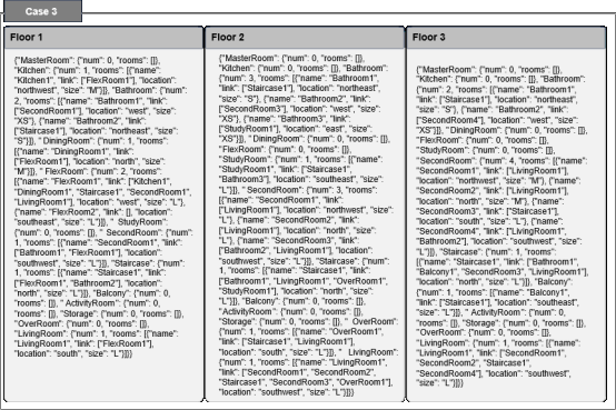
Figure E.3 JSON inputs of Case 3
E.2 Initial Component Section Dimensions and Concrete Strength Grades of Each Case
This section lists the initial conditions adopted for the seismic design of the three cases.
Table E.1 Initial conditions of Case 1 for the seismic design
|
Story |
1 |
2 |
3 |
|
Wall thickness (mm) |
200 |
200 |
200 |
|
Beam height (mm) |
500 |
500 |
500 |
|
Slab thickness (mm) |
150 |
150 |
150 |
|
Beam concrete grade |
C30 |
C30 |
C30 |
|
Slab concrete grade |
C30 |
C30 |
C30 |
|
Reinforcement grade |
HRB400 |
HRB400 |
HRB400 |
|
Story height (mm) |
3600 |
3300 |
3000 |
Table E.2 Initial conditions of Case 2 for the seismic design
|
Story |
1 |
2 |
3 |
|
Wall thickness (mm) |
200 |
200 |
200 |
|
Beam height (mm) |
500 |
500 |
500 |
|
Slab thickness (mm) |
150 |
150 |
150 |
|
Beam concrete grade |
C35 |
C35 |
C35 |
|
Slab concrete grade |
C30 |
C30 |
C30 |
|
Reinforcement grade |
HRB400 |
HRB400 |
HRB400 |
|
Story height (mm) |
3600 |
3000 |
2800 |
Table E.3 Initial conditions of Case 3 for the seismic design
|
Story |
1 |
2 |
3 |
|
Wall thickness (mm) |
200 |
200 |
200 |
|
Beam height (mm) |
500 |
500 |
500 |
|
Slab thickness (mm) |
150 |
150 |
150 |
|
Beam concrete grade |
C35 |
C35 |
C35 |
|
Slab concrete grade |
C30 |
C30 |
C30 |
|
Reinforcement grade |
HRB400 |
HRB400 |
HRB400 |
|
Story height (mm) |
3600 |
3000 |
3000 |
Appendix F. ChatHouse Platform
To further demonstrate the accessibility and potential practical applicability of the floor plan design model in our study, an online deployment platform, namely the ChatHouse platform, is provided. The platform is developed based on the floor plan generation model and serves as an interactive interface for model inference. It allows readers to test the model without directly preparing model-specific input files or running the model locally.
In the platform, users can manually draw the building outline, specify the room types and room quantities, and define room adjacency relationships through a bubble diagram interface. Based on these requirements, the platform automatically converts the input information into JSON text that is consistent with the inference format of our model. The generated JSON file is then submitted to the backend model for inference, and the corresponding floor plan layout is returned as the output. This process provides a more intuitive way to examine the generation behavior of the model under different design conditions.
The ChatHouse platform is provided for academic research, model demonstration, and non-commercial trial use only. Users may use the platform to reproduce, examine, and evaluate the floor plan generation capability of the model for research and educational purposes. Commercial use, redistribution, or deployment of the platform or generated results for engineering practice without permission is not allowed.
It should also be noted that the layouts generated by the platform are intended for preliminary design exploration. They do not replace professional architectural design, engineering review, or code compliance checking. Any generated result intended for practical use should be further examined, refined, and verified by qualified professionals.
The platform is available at: https://ai-structure.com/floor-plan-design/