|
(a)
Multi-layer shell
element
(b)
Location of the rebar layers
Figure
1. The Principal of multi-layer shell element
In this research, the corresponding multi-dimensional concrete
material model, steel reinforcement model and multi-layer shell element model
are developed in OpenSEES. The multi-layer shell element is based on the ShellMITC4
element that is already provided by OpenSEES. The framework of the proposed
multi-layer shell element in OpenSEES is shown in Figure 2.
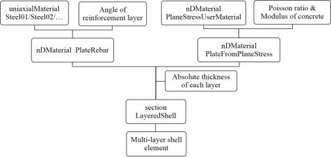
Figure 2 .The framework of the multi-layer
shell element in OpenSEES
1 Multi-dimensional concrete model.
This command is used to create the multi-dimensional concrete
material model that is based on the damage mechanism and smeared crack model.
|
nDmaterial
PlaneStressUserMaterial $matTag 40 7 $fc $ft $fcu $epsc0 $epscu $epstu
$stc
|
|
$matTag
|
integer tag identifying material
|
|
$fc
|
concrete compressive strength at 28 days (positive)
|
|
$ft
|
concrete tensile strength (positive)
|
|
$fcu
|
concrete crushing strength (negative)
|
|
$epsc0
|
concrete strain at maximum strength (negative)
|
|
$epscu
|
concrete strain at crushing strength (negative)
|
|
$epstu
|
ultimate tensile strain (positive)
|
|
$stc
|
shear retention factor
|
|
nDmaterial PlateFromPlaneStress
$newmatTag $matTag $OutofPlaneModulus
|
|
$newmatTag
|
new integer tag identifying material deriving from
pre-defined PlaneStressUserMaterial
|
|
$matTag
|
integer tag identifying PlaneStressUserMaterial
|
|
$OutofPlaneModulus
|
shear modulus of out plane
|
2. Multi-dimensional Reinforcement Material
This command is used to create the multi-dimensional reinforcement
material.
|
nDmaterial PlateRebar $newmatTag
$matTag $sita
|
|
$newmatTag
|
new integer tag identifying material deriving from
pre-defined uniaxial steel material
|
|
$matTag
|
integer tag identifying uniaxial steel material
|
|
$sita
|
define the angle of steel layer, 90 º (longitudinal
steel), 0º (tranverse steel)
|
3. Define the Section of the Multi-layer Shell element
This command will create the section of the multi-layer
shell element, including the multi-dimensional concrete, reinforcement material
and the corresponding thickness.
|
section LayeredShell $sectionTag
$nLayers $matTag1 $thickness1...$matTagn $thicknessn
|
|
$sectionTag
|
unique tag among sections
|
|
$nLayers
|
total numbers of layers
|
|
$matTag1
|
material tag of first layer
|
|
$thickness1
|
thickness of first layer
|
|
¡.
|
|
|
$matTagn
|
material tag of last layer
|
|
$thicknessn
|
thickness of last layer
|
4. Examples
Two solid shear wall specimens are chosen to demonstrate
the feasibility of the proposed multi-layer shell element.
Table 1. Parameters of the specimen
|
Specimen
|
Dimension
(mm)
(H
¡° W ¡° t)
|
High/width
|
Concrete
strength
|
Width
of boundary zone
|
Axial
load ratio
|
Longitude
reinforcement
|
Stirrups
|
|
SW1-1
|
2000¡°1000¡°125
|
2.0
|
C30
|
200
|
0.1
|
6D10
|
D6@80
|
|
SW2-1
|
1000¡°1000¡°125
|
1.0
|
C40
|
200
|
0.3
|
6D10
|
D6@80
|
Table 2. Parameters of the concrete
|
Specimen
|
fc(MPa)
|
ft(MPa)
|
fcu(MPa)
|
epsc0
|
epscu
|
epstu
|
stc
|
|
SW1-1
|
20.7
|
2.07
|
-4.14
|
-0.002
|
-0.006
|
0.001
|
0.08
|
|
SW2-1
|
30.8
|
3.08
|
-6.16
|
-0.002
|
-0.005
|
0.001
|
0.05
|
The stirrups is smeared into orthotropic rebar layers along
0º direction, whereas the longitude reinforcement is smeared into orthotropic
rebar layers along 90º direction. The concentrated reinforcement in boundary
zone is modeled with truss element, whose node is shared with the shell element
to achieve the displacement compatibility.
The boundary zone and the other part of the wall are separately
defined with two different multi-layer sections. The boundary zone is divided
into 10 layers while the wall is divided into 8 layers.
|
|
|
|
(a) SW1-1
|
(b) SW2-1
|
Figure 3. Force-displacement of the specimens
Test date: Zhang HM, Study on the Performance-based
Seismic Design Method for Shear Wall Structures, Doctoral Thesis, Tongji University,
Shanghai, 2007.
By:
Linlin XIE and Kaiqi LIN
Supervised
by: Xinzheng LU, Yuli HUANG (ARUP) and Lieping YE
Download
Address http://www.luxinzheng.net/download/OpenSEES/THUShell.zip
|