|
Introduction:
Nonlinear simulations
for structures under disasters have been widely focused on in recent years. However, precise modeling
for the nonlinear behavior of reinforced concrete (RC) shear walls, which are
the major lateral-force-resistant structural member in high-rise buildings,
still has not been successfully solved. As the cross section of the shear wall
member is much bigger than that of the beam and column member, its deformation
behavior under the lateral load is more complicated and the research has focused
on the nonlinear analysis model for shear wall at home and abroad until now.
In this paper, based on the principles of composite material mechanics, a multi-layer
shell element model is proposed to simulate the coupled in-plane/out-plane bending
or the coupled in-plane bending-shear nonlinear behaviors of RC shear wall.
At the element level, the model uses the shell element that is made up of multiple
layers with different thickness and different material models (concrete or rebar)
are assigned to various layers. Since the model relates the nonlinear behaviors
of the shear wall element to the constitutive relations of concrete and steel
directly, it
has many advantages in the description of the actual complicated nonlinear behaviors.
In the nonlinear analysis for the concrete structures, the constitutive relation
of the concrete has great effect on the analysis results. Although the traditional
elasto-plastic-fracture constitutive model for concrete is efficient, it does
not give satisfying performance for concrete under complicated stress condition.
So at the material constitution level, a novel concrete constitutive model,
referred as microplane model, which is originally proposed by Bazant et al.,
is developed to provide a better simulation for concrete in shear wall under
complicated stress conditions and stress histories. In order to validate the
capacity of the proposed shear wall model, three shear walls with different
nonlinear behaviors under given load cases were taken as examples. Pushover
analysis and static cyclic loading analysis were carried out on these shear
walls with the proposed shear wall model to illustrate the capacity
of the proposed model.
Multi-layer
shell element
The proposed
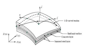
multi-layer shell element is based on the principles of composite material mechanics and it can simulate the coupled in-plane/out-plane bending
and the coupled in-plane bending-shear nonlinear behaviors of RC shear wall. Basic principles of multi-layer shell element
are illustrated by Figure 1. The shell element is made up of many layers with different thickness.
And different material properties are assigned to various layers. This means that the rebars are smeared into one layer
or more. During the finite element calculation, the axial strain and curvature
of the middle layer can be obtained in one element. Then according to the assumption
that plane remains plane, the strains and the curvatures of the other layers
can be calculated. And then the corresponding stress will be calculated through
the constitutive relations of the material assigned
to the layer. From the above principles, it
is seen that the structural
performance of the shear wall can be directly connected with the material constitutive
law.
|
|
|
Figure 1: Multi-layer shell
element
|
|
|
|
Figure 2: Settings of the rebar layers
|
The constitutive
model of the rebars is set as the perfect elasto-plastic model.
Because the rebars in different directions are smeared into one layer, so if
the ratios of the amounts of the distributing rebars to the concrete in the
longitudinal direction and transverse direction are the same, the rebar layer
can be set as isotropic. But if the ratios in the two directions are different,
the rebar layer should be set as orthotropic with two principal axes as shown in Figure 2. And in different principal axis, the stiffness is set different according
to the ratio of the amount of rebars to concrete to simulate longitudinal rebars
and transverse rebars respectively. The constitutive model of the concrete is
the microplane model which will be illuminated in
detail in the next section.
Since the model
relates the nonlinear behaviors of the shear wall element to the constitutive
relations of concrete and steel directly,
it has many advantages in the description of the actual complicated nonlinear
behaviors as compared with the existing equivalent-beam model, equivalent-truss
model and the multi-component-in-parallel model for shear wall[1].
Microplane
Constitutive Model for Concrete
Concrete is a kind of brittle-plastic
material and its relation between the stress and strain under the multi-axial
loads is very complicated, so in the nonlinear analysis for the concrete structures,
the constitutive model of the concrete has great effect on the analysis results.
Usually the precision and the validity of the shear wall model is mainly decided
by the precision and the validity of the constitutive model for concrete. The
traditional elasto-plastic-fracture constitutive models for concrete are macroscopic
models. Although great success has been reached in the past, the macroscopic
models now seem to have entered a period of diminishing returns, in which a
great effort yields only little improvement[2]. When the concrete
is under complicated stress condition, these models often can��t give satisfying
performance for the concrete material. So at the material constitution level,
a novel concrete constitutive model, referred as micro-plane model, which is
originally proposed by Bazant et al.[5], is introduced in the proposed
shear wall model and this is achieved by developing the subroutine based on
MSC.Marc.
As one kind of the micromechanics
models, microplane model considers the microstructure of the material.
In the microplane model, a set of
planes of any orientations in the material microstructure called as the microplane
are referred. And the constitutive law is formulated in terms of vectors rather
than tensors, as a relation between the stress and strain components on these
microplanes. By integrating over the all the spatial directions, the microplane
model can satisfy the tensor invariant requirement automatically on the macroscopic
and conceptual simplicity is achieved. Due to the research work of P. Bazant
et al.[2,3,4,5], there have been much progress on microplane model
during the last 20 years. In the first version, the microplane model of concrete
was only devised for tensile fracturing, but now it has been updated to the
fourth version which can characterize the complicated nonlinear triaxial behavior
as well as the deformation behavior under the cyclic load. The results of the
numerical analysis for basic loading types with the microplane model have been
compared with many actual test results and it is shown that microplane models
can characterize the responses of concrete under different loading types[2].
Demonstration
cases
In order to
validate the capacity of the proposed shear wall model, three shear walls were
selected as the demonstration models. Pushover analysis and static cyclic
loading analysis were carried out on these shear walls with the proposed shear
wall model.
For the shear
wall, the lengths in two directions in the wall plane are both much larger than
the thickness of the wall. This is much different from the beam and column members,
and it will lead to bending deformations as well as shear deformations which
usually can��t be neglected at the same time when the wall is under lateral load
in plane. These shear deformations in the wall plane have an important effect on the failure type of the wall and this complicated behavior causes the nonlinear
analysis of the shear wall become much more difficult than the beam element
directly. Because the shear span ratio of the wall is a main factor which affects
the shear deformation behavior, case 1 and case 2 will simulate the coupled in-plane bending-shear nonlinear behaviors of RC shear wall with different
shear span ratios respectively. And case 3 simulates the out-plane bending behaviors of RC shear
wall. Figure 3 shows
the finite element model in
case 1, and the finite element model for case 2 and case 3 are similar to case 1.

 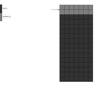
Figure 3: Finite element model
in case 1
Case 1:
The shear span ratio of the shear
wall in this case is 2. For pushover analysis, the in-plane lateral load increased
by step is only applied at the top of the wall. Besides, static cyclic loading
process is also analyzed. In both the two analysis, the vertical load with the
axial force ratio of 0.2 is applied in advance at the top of the wall. The load-displacement
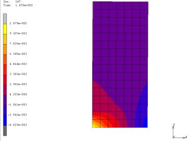
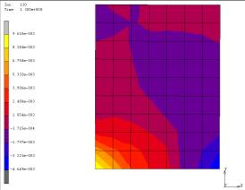
curve for pushover is plotted in Figure 4. Besides, the contour of the principal
major strain at the state with the peak load in pushover is plotted in Figure
6.
From Figure 4, it can be seen that
the utmost loading capacity of the shear wall is about 170kN with the displacement
of about 7mm. And Figure 6 shows that at this time, quite a lot of concrete
elements at the bottom had cracked and most tensile rebars had yielded. After
that, as the crack expanded, the compressive area was getting smaller and smaller,
which caused the loading capacity drop. It can be concluded that the failure
type of the wall in this case is mainly in-plane bending failure and shear deformation
doesn��t play an important part in the response of the shear wall.
Displacement of the shear wall along
the height at different stages in pushover is shown in Figure 5, indicating
that the shape of lateral displacement is of bending type. So the deformation
behavior of shear wall structure is clearly illustrated here.
|
|
|
|
Figure 4: Load-Displacement
curve for pushover
|
Figure 5: Displacement
along the height at different stages in pushover
|
|
|
|
Figure 6: Contour of the
principal major strain at the state with the peak load in pushover
|
|
|
|
Figure 7: Load-Displacement
curve for cyclic loading
|
Load-Displacement
curve for cyclic loading is plotted in
Figure 7 and the pinch effect is shown in it.
This reflects the actual response characteristics of the shear wall under cyclic
load clearly. Besides, exterior envelope of the load-displacement curve has
entered the softening part, which indicates that the microplane model can simulate
the damage accumulation of shear wall during the cyclic loading process precisely.
This is very important for the performance-based design of structures under
disaster loads.
Case 2:
The shear span ratio of the shear
wall in this case is 1, therefore this wall belongs to the type of short wall
and the in-plane shear failure always occurs in this type of walls.
The load-displacement curve is shown
in Figure 8 and the curve of the same relation in case 1 is also shown in Figure
8 for a comparison. It can be seen that the stiffness and the loading capacity
of the wall in case 2 are much larger than that in case 1 because the shear
span ratio has affected the response characteristic of the shear wall under
the lateral load. Similarly to case 1, the contour of the principal major strain
at the state with the peak load is plotted in Figure 9 to show more details
about the failure type of the wall. In fact, Figure 9 shows that at state of
the maximum loading capacity, a compressive column had formed in the diagonal
direction of the wall. After that, the concrete of the diagonal compressive
column was crushed and quitted the loading gradually, which caused the loading
capacity of the wall drop. But this process is more brittle than the descending
process in case 1. This can be proved by comparing the descending part of the
two curves in Figure 8. This is a typical in-plane shear failure process of
shear wall. Obviously, shear deformation plays an important part in the response
of the shear wall in this case and the shear failure process has much more brittleness
than the bending failure process.
|
|
|
|
Figure 8: Load-Displacement
curve for pushover
|
Figure 9: Contour of the
principal major strain at the state with the peak load in pushover.
|
|
|
|
Figure 10: Load-Displacement
curve for cyclic loading
|
In Figure 10, the pinch effect can
still be seen in the load-displacement curve for cyclic loading. And similarly
to Figure 7, exterior envelope of the load-displacement curve has entered the
softening part because of the damage accumulation of shear wall during the cyclic
loading process. But the exterior envelope of the load-displacement curve in
case 2 is steeper than case 1 because the shear failure process has much more
brittleness than the bending failure process
Case 3:
In the actual
shear wall structures, the shear walls are laid in both longitudinal and transverse
directions. When the lateral load is applied to structure in one direction,
the response of the wall with the plane in the same direction will present the
coupled in-plane bending-shear nonlinear behavior just as in the above case 1 and case 2. But the wall with the plane perpendicular
to the loading direction will bend out of the loading plane and present the
out-plane bending behavior. This must be considered in the finite element analysis
for shear wall structures.
In case 3, the geometric model is
the same as in case 1. To study the out-plane bending behavior of shear wall,
the out-plane lateral load increased by step is applied at the top of the wall,
and the vertical load with different axial force ratios is applied in advance
at the top of the wall.
Figure 11 shows the relation between the lateral load
and the lateral displacement at the top of the wall under different axial forces
studied. Because the thickness of the shear wall is much smaller than the height,
the out-plane bending behavior of the shear wall is very similar to the bending
behavior of the 1-D beam element. This can be proved from Figure 11.
Obviously, the program can obtain the softening out-plane
bending behavior of the wall. Besides, the plot showing the relation between
the maximum moment Mmax and corresponding axial force ratio in Figure
12, indicates accords with the existing theory[6] as well. From these
analysis results, it can be concluded that the proposed multi-layer shell element
model with the microplane constitutive models for the concrete does well in
simulating the out-plane bending behavior of the shear wall under different
axial forces.
|
|
|
|
Figure 11: Load-Displacement
curves under different axial force ratios in case 3
|
Figure 12: Relation between different axial force ratios and maximum
bending moments
|
Conclusion
The proposed
multi-layer shell element model
based on the principles of
composite material mechanics relates the nonlinear behaviors
of the shear wall element to the constitutive relations of concrete and steel
directly, and therefore it has many advantages in the description of the actual complicated
nonlinear behaviors. And at the material constitution
level, a novel concrete constitutive model, referred as micro-plane model
is introduced to provide a
better simulation for concrete in shear wall under complicated stress conditions
and stress histories. The simulation results show
that the multi-layer shell element model can correctly simulate the coupled in-plane/out-plane
bending failure for tall walls and the coupled in-plane bending-shear failure
for short walls. And with micro-plane concrete constitutive law, the cycle behavior
and the damage accumulation of shear wall can be precisely modeled, which is
very important for the performance-based design of structures under disaster
loads.
|