Mechanism of Passive Control RC Frame with High Strength Reinforcements and its Potential Benefits against Earthquakes

Asad Ullah Qazi1, Lieping Ye1,2, Xinzheng Lu1,2

1 Department of Civil Engineering, Tsinghua University, Beijing, China, 100084

2 Key Laboratory of Structural Engineering and Vibration of China Education Ministry

Tsinghua Science and Technology, 11(6), 2006, 640-647

Download PDF version

Recommended reading: "Elasto-plastic analysis of buildings against earthquake", Beijing: China Architecture and Building Press, 2009.

Abstract: In the present world major catastrophe is yet severe earthquakes. Many devices which include in active, hybrid and semi-active structural control systems as controllable force devices are costly in their construction and maintenance. The mechanism of the passive control RC frame (PCRCF) reinforced with high strength reinforcements only in columns presented here is an attempt to provide structural systems more resistance against lateral earthquake loadings at comparatively lower cost. The concept is demonstrated by nonlinear static analysis by fiber model for a single story single bay frame. The study revealed that use of high performance steel in columns can prevent formation of plastic hinges at the critical column base sections and failure always initiated by yielding of reinforcement at beam ends. Further after experiencing severe lateral drift, PCRCF showed small residual displacement as compared to ordinary RC frame. Rehabilitation and strengthening of the frames can be made easier for PCRCF.

Keywords:  earthquake, passive control, high strength reinforcement, failure mechanism, residual displacement

1 Introduction    


In most reinforced concrete (RC) structures a large stiffness is desired in order to limit structural deformation under service load conditions. In seismic resistant structures, however the energy dissipation demands impose the inelastic deformation permission in special detailed regions of structure when the severe earthquake attacks. In particular moment resistant frames designed according to the strong column/weak beam concept are expected to undergo inelastic deformations by formation of plastic hinges in the beams. The columns are supposed to remain elastic in order to maintain vertical load carrying capacity and prevent possible collapse. Although the required flexural strength differential between beams and columns at joint locations enforces this ideal frame deformation mechanism, however it is shown that the deformations at the base of the first story columns must be excessive to initiate the frame sway (Paulay and Priestley[1]). Therefore the formation of plastic hinges at the base of the first story columns is inevitable as shown in figure 1. Although in some instances the formation of plastic hinges at the column bases may not be so critical regarding the safety of the structure, but it requires extensive rehabilitation efforts. Moreover the frame does not possess the recentring ability after undergoing severe lateral drift during strong shaking and the chances of complete demolition of the structure are always there in case of excessive yielding at the column base sections. Furthermore, the possibility of exceeding the moment capacity at the top of columns still exists, and the sway failure mechanism can be formed as shown in figure 2.


Îı¾¿ò:                                  
Fig.1 Strong Column/Weak Beam Configuration                 Fig. 2 Soft First Story Failure

The purpose of this paper is to demonstrate the alleviation and prevention of the formation of plastic hinges in frame columns by introducing high strength reinforcement in RC frame column, which is called here after as  passive controlled RC frame (PCRCF) with high strength steel reinforcement.

2 Concept of PCRCF

A conventional designed moment resistant frame usually can not successfully develop its ability against unexpected earthquake loadings due to limited flexural strength and by the formation of plastic hinges at the base of the first story columns. Further excessive yielding at the column base sections may lead to eventual collapse and soft first story failure mechanism is difficult to avoid. Moreover even after survival of structure against extreme lateral drift the large residual deformations may dictate need for complete demolition. By introducing high strength reinforcement in columns, PCRCF can safeguards its column base section from excessive yielding and resultantly can adjust structural characteristics by using the reserve flexural strength at the column base sections. Further the yielding will only occur at beams ends. Due to elasticity of high strength reinforcement in columns recentring capacity can be improved with the reduced residual lateral displacement under extreme lateral loading. Resultantly repairs can be made easier by following this concept.

Seismic behavior of the structures has been the subject of extensive study over the last several decades. To date the basic philosophy behind seismic resistant structures is that a structure should not collapse during severe earthquake, although it may undergo structural as well as non structural damage. However reduced residual displacement and minimum rehabilitation demands after seismic event are becoming the desired objectives in recent years.

So far a large number of passive control systems have been developed and installed. Furthermore structural systems designed with self centering capabilities after experiencing large nonlinear deformations commonly use un-bonded post tensioned steel tendons in various types of construction, such as in pre-cast concrete by Priestley et al[2]; El-Sheikh et al[3]; Kurrama et al[4], in steel structures by Ricles et al[5], in partially prestressed concrete for bridge piers by Wael and Hiroshi [6] and in unbonded post tensioned bridge piers by Kawan and Billington [7].

Concrete ductility with fiber reinforced polymer (FRP) tendons has been studied by Namman and Jeong [8], Alsayed and Alhozaimy [9] as well as hybrid FRP reinforcement with inherent ductility by Harris et al [10]. However with the development in the Engineered Cementitious Composites (ECC) a frame system with intrinsic collapse prevention capabilities has also been proposed by Fischer and Victor [11] by utilizing ECC and FRP reinforcement in columns.

The suggested ideal frame deformation sequence is shown in figure 3. Besides reduced residual displacements the frame showed absence of potential collapse mechanism by avoiding yielding at the column base sections. However ECC being a new innovative material hence scarcely introduced to construction industry. It is still desired to explore cheaper materials and to investigate the conventional materials in achievement of this ideal proposed mechanism.

In the present study it is suggested that the ideal frame mechanism can be achieved by using ordinary conventional concrete with high strength steel reinforcement.

3 Analysis models and method

To demonstrate the PCRCF mechanism and to investigate the behavioral difference between ordinary frame and the PCRCF, two single story single bay frames, one ordinary frame (ODF) and another PCRCF, were analyzed.  The behaviors and failure mechanism of both the frames are estimated with nonlinear static analysis. The figure 4 represents the selected geometry and the loading pattern for both the frames.

For describing the behaviors of the both frames, the critical sections such as Left Column Base (LCB), Left Column Top (LCT), Beam Left End (BLE), Beam Right End (BRE), Right Column Top (RCT) and the Right Column Bottom (RCB) are marked. The lateral point load (P) applied at the top left end of frame and the dead axial load (AL) equal to 10% of the gross capacity of columns was applied on columns. Beam was loaded with a uniformly distributed load (UDL) of 18 kN / m. Material self weight of the frame was also considered in the analysis. The frame was designed following the ACI Code specifications and the details of the selected strengths and steel ratios are given in table 1 and 2 respectively.

Table 1 Material strength properties used in the analysis

Frame Analyzed

Steel Yield Strength (MPa)

Concrete Compressive Strength (MPa)

Columns

Beam

Columns

Beam

ODF

400

400

40

30

PCRCF

1860

400

40

30

Table 2 Selected steel area ratios in frames

Frame Analyzed

Steel Ratio in Columns

As/(b¡Áh)

Tensile Steel Ratio in Beam

As/(b¡Ád)

ODF

0.02

0.02

PCRCF

0.02

0.02

Both the frames were analyzed on MSC.Marc using beam element 52 with hypoelastic material option. A fiber model programmed with user subroutine UBEAM is used to simulate the section behavior in the analysis. Three different section discretization schemes with 100, 64 and 36 concrete fibers while keeping the steel fibers 4 in each case were investigated to confirm the convergence requirement with a relative force tolerance of 0.1. The cover and the core concrete fiber areas were different however as 25 mm clear cover was selected for all the sections. It is shown that the scheme with 36 concrete and 4 steel fibers one at each corner, as shown in the figure 5, meet the convergence requirement.

Finite element length was kept equal to 300 mm for the frame elements in both the frames. Further at critical sections where there were more chances of distress it was reduced to 100 mm. The finite element model used for analysis is also shown in figure 6. It is noticeable that the selected beam element 52 in MSC.MARC has three integration points so the results were further revealed at the three sections along the length selected.

Concrete and the steel fibers were given uniaxial stress strain relations as shown in the figure 7 and figure 8 respectively. The unconfined concrete stress strain relation with e 0=0.002 and e u=0.004 was selected for concrete fibers. The elasto-plastic model is used to describe the stress strain relation of steel. Because of the smaller contribution to ultimate strength the concrete tensile strength was considered zero during analysis. The ordinary and high performance steel yield strains (¦Åy) were selected as 0.002 and 0.009 respectively. The lateral load P for both the frames was selected as static load increased gradually until the failure state was attained.

Fig. 6 Finite element model used for analysis


4 Analysis results

4.1  Response stages

For comparative study, both the ODF and PCRCF were analyzed and the results at each of the response stages were described. The lateral load and displacement relations are shown in figures 9 for the ODF and PCRCF. The lateral load displacement relation of both the frames can be divided into four response stages. The end of each response stage is marked as A, B, C and D. The four response stages are described as following:

The response stage 1 (O-A) for both the ODF and PCRCF ranged from start of lateral load application till the initiation of the yielding of steel anywhere in the frames started. It is noticed during analysis that always the critical sections shown in the figure 4 dominated in frame failure initiation. The response stage 2 (A-B) ranged from steel yield initiation till the concrete design compressive strain shown as e 0=0.002 reached anywhere in the frame. The   response stage 3 (B-C) ended when anywhere in the frames concrete reached its maximum useable strain which was selected as 0.0035. The response stage 4 (C-D) which was also the termination of the analysis was selected when concrete reached its ultimate compressive strain  e u=0.004.

The selection of these four response stages were based in accordance with the performance, rehabilitation and the strengthening demands imposed on the frames. The main goal was to get a better comparison of performance between both the frames in terms of load bearing capacity, the failure initiation locations, repair or rehabilitation demands in both the frames at the end of each response stage. Moreover in order to check the residual deformation the unloading was performed at each response stage end and is also compared in the figure 11 for both the frames.

4.2  Loading performance

The results for the lateral load verses displacement for ODF and the PCRCF at the end of each response stage are given in table 3. Concrete and steel fiber strains at the end of each response stage at critical sections are also summarized in table 4.

It can be inferred that at the end of stage 1 marked as A in the figure 9 that the PCRCF has resisted more lateral

Table 3 Loading performance at the end of each response stage for ODF and PCRCF

Response

Stage

Lateral Load (kN)

Lateral Displacement (mm)

PCRCF

ODF

PCRCF

ODF

1 (A)

481

331

35.0

22.0

2 (B)

494

400

38.0

36.0

3 (C)

624

425

59.0

60.0

4 (D)

650

426

65.0

68.0

load almost 150 kN more than the ODF. Moreover it was noticed during analysis that yielding occurred at the BRE section for PCRCF as compared to the more critical and vital LCB and RCB sections for ODF. This behavioral difference at the end of stage 1 showed the better performance of PCRCF as if the rehabilitation or repairs need to be carried out it is easier and cheaper to strengthen the cracked or yielded beams as compared to the more vital column base sections at restricted locations.

The end of stage 2, marked as B in figure 9 for both the frames, indicates that PCRCF still has resisted more lateral load before reaching of the concrete design compressive strain anywhere in the frame. The analysis shows that reaching of concrete design compressive strain occurred at RCB sections for both the ODF and PCRCF, however, at different lateral load and lateral displacements. The difference between the lateral load resistances at the end of this stage between both the frames was almost 94 kN. PCRCF still dominates in the resistance capacity at the end of this response stage. Although at the end of this response stage the concrete design compressive strain in both the frames Table 4: Condition of each of the controlling Sections at the end of each response stage for ODF and PCRCF

(a)     Response stage A

Sections

Compressive Strain of concrete

Tensile Strain of reinforcement

PCRCF

ODF

PCRCF

ODF

RCB

LCB

RCT

LCT

BLE

BRE

< 0.002

< 0.002

<¦Åy

0.002

< 0.002

< 0.002

<¦Åy

<¦Åy

< 0.002

< 0.002

<¦Åy

<¦Åy

< 0.002

< 0.002

<¦Åy

<¦Åy

< 0.002

< 0.002

<¦Åy

<¦Åy

< 0.002

< 0.002

0.002

<¦Åy

(b) Response stage B

Sections

Compressive Strain of concrete

Tensile Strain of reinforcement

PCRCF

ODF

PCRCF

ODF


RCB

LCB

RCT

LCT

BLE

BRE

0.002

0.002

<¦Åy

0.0068

< 0.002

< 0.002

<¦Åy

0.0064

< 0.002

< 0.002

<¦Åy

0.0021

< 0.002

< 0.002

<¦Åy

<¦Åy

< 0.002

< 0.002

<¦Åy

<¦Åy

< 0.002

< 0.002

0.0033

0.0022

(c) Response Stage C

Sections

Compressive Strain of concrete

Tensile Strain of reinforcement

PCRCF

ODF

PCRCF

ODF

RCB

LCB

RCT

LCT

BLE

BRE

0.0032

0.0035

<¦Åy

0.0143

0.0025

0.0031

<¦Åy

0.0141

< 0.002

< 0.002

<¦Åy

0.0058

< 0.002

< 0.002

<¦Åy

0.0065

0.0024

< 0.002

0.0099

0.002

0.0035

< 0.002

0.016

0.0066

(d) Response Stage D

Sections

Compressive Strain of concrete

Tensile Strain of reinforcement

PCRCF

ODF

PCRCF

ODF

RCB

LCB

RCT

LCT

BLE

BRE

0.0035

0.004

<¦Åy

0.0171

0.0027

0.0036

<¦Åy

0.0171

< 0.002

0.0021

<¦Åy

0.0072

< 0.002

0.0022

<¦Åy

0.009

0.0026

< 0.002

0.0122

0.0021

0.004

0.002

0.0177

0.0082

occurred at the same RCB sections but still the response had one major difference between both the frames. As in case of ODF the concrete reached its design compressive strain at the same RCB section where yielding of steel already had occurred at the end of the response stage 1. But in case of PCRCF the RCB section has not shown any sign of yielding and only concrete reached its design compressive strain which can also be controlled by providing confinement at the column base sections in case of PCRCF. The provision of confinement in case of ODF would yield little benefit as the yielding of the reinforcement at column base section would demand extensive rehabilitation efforts.

The end of stage 3 marked as C in figure 9 further revealed the more lateral load capacity resistance of the PCRCF. The difference between load resistances at this stage was seen almost equal to 199 kN between both the frames. The end of this stage approached when concrete reached its maximum useable strain of 0.0035 anywhere in the frame. It was evidenced at the end of this stage that ODF reached the useable concrete strain 0.0035 at the column base sections (RCB & LCB) while PCRCF reached this selected strain at BRE and the RCB sections almost simultaneously. As mentioned above that the absence of yielding of steel at the column base sections can offer advantage in the presence of confinement at the column base sections in case of PCRCF. Compared with PCRCF, the ODF at lower lateral load reached at this stage and the rehabilitation and strengthening demands at restricted column base sections are more desired because of reinforcement yielding.

At the end of failure stage 4, marked as D in the figure 9, further highlights the dominance of PCRCF and the lateral load resistance difference between the frames was noticed almost equal to 224 kN. In case of PCRCF still the vital column base sections LCB and RCB were seen safe from yielding of reinforcement, while severe yielding along with concrete failure in case of ODF is seen. Hence at the failure stage rehabilitation and strengthening would be much easier and comparatively cheaper in case of PCRCF as compared to ODF. It is also noticeable that severe yielding of the column base section might dictate the complete demolition of the frame rather then strengthening and rehabilitation as might be required in case of the PCRCF.

4.3 Failure mechanism

From the observed fiber strains during analysis which are summarized in table 4 the extent of yielding at the four response stages at the critical sections can easily be studied. Moreover the strains also provide guidance in the exact determination of the failure mechanism in each of the frame studied. From the available data in table 4 figure 10 has been drawn to show the location of plastic hinges in the frames at the 4 response stages studied.

It is evident from figure 10 and values of the fiber strains given in table 4 that at response stage 2 mechanism developed incase of ODF however PCRCF still have shown yielding only at BRE and further even up to stage 4 potential failure mechanism not appeared in the case of PCRCF. After first significant yield at RCB the ODF has shown displacement ductility of smaller magnitude as compared to the PCRCF. It is evident from the lateral displacement values given in table 3 that ODF at the end of response stage 1 has shown 22 mm lateral displacement and at 36 mm when response stage 2 ended failure mechanism developed in case of ODF. However PCRCF laterally displaced to 35 mm at the end of response stage 1 and until the end of 3rd response stage it laterally displaced to    60 mm with yielding of beam at BLE and BRE sections. It is further noticeable that the ODF is almost yielded at all the critical sections significantly at the end of the response stage 3. However in comparison the PCRCF only reached its tensile yield strain at the BLE and the BRE sections against more lateral load as compared to the ODF.

4.4  Unloading performance

In order to monitor the residual deformation in both the frames after unloading, separate analysis runs were carried out by loading and unloading for both the frames. The frames were laterally loaded gradually at their respective lateral loads at the each response stage end and then gradual unloading carried out.

The unloading was schemed inside MSC.MARC by allowing the gradual removal of the lateral load at the same application. The loading unloading curves at each response stage are shown in figures 11. For both the frames the residual deformation seen at the end of loading unloading cycle are also given in table 5.

It is evident from the residual displacement values given in table 5 and from figures 11 that at the first cycle of loading and unloading not much of the residual deformation seen in both the frames. This is because that ODF was unloaded when yielding just started and PCRCF was still in its elastic range. However in the oncoming loading and unloading cycles the difference between residual deformations gradually started increasing and the PCRCF showed considerably smaller residual deformations as compared to the ODF at the latter response stages.

Load Unload Cycle

Lateral Load before Unloading (kN)

Residual Deformation (mm)

PCRCF

ODF

PCRCF

ODF

(O-A-O)

481

331

0.5

0.3

(O-B-O)

494

400

1.0

7.0

(O-C-O)

624

425

9.0

28.0

(O-D-O)

650

426

12.0

36.0

Îı¾¿ò: Table 5. Residual displacements at unloading in ODF and PCRCF
 at each response stage

5 Conclusions

In this paper the mechanism of the passive control RC frame with high strength reinforcement and its expected potential benefits against earthquakes has been compared 
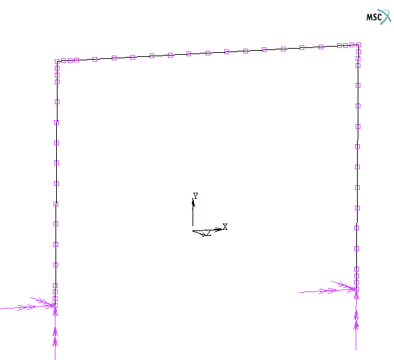
with the ordinary RC frame. For this purpose two single bay single story frames were selected and their response compared. From the above mentioned mechanism demonstration the following conclusions can be drawn.
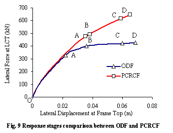
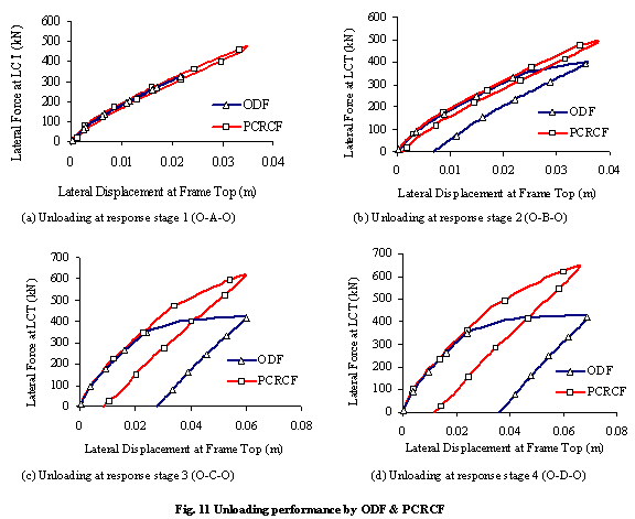
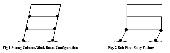
1.         PCRCF can prevent soft story failure mechanism and provide more increased lateral load resistance capacity with less reparable cost by simple replacement of ordinary conventional steel in the frame columns with high tensile strength steel.

2.         PCRCF shows signs of distress mainly at the beam end sections which are potentially safe from stability point of view of entire frame as compared with ODF where column base sections are badly yielded.

3.         As compared to ODF, PCRCF rehabilitation and strengthening can be done more easily because of easier approach to beam end sections as compared to the more restricted column base sections.

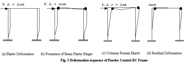
4.         PCRCF can reduce the residual displacement in the frames after going through lateral displacement.

5.          PCRCF mechanism can reduce the chances of complete demolition as a result of excessive yielding at column base sections.

Besides the above conclusions, it could be understood that the performance of PCRCF can further be improved by providing concrete confinement at the beam ends and column base sections since confinement at the beam ends would increase ultimate deformation capacity at the plastic hinges and at the column base sections with high strength steel would increase the deformation capacity of the whole frame.

Since the demonstration of the PCRCF mechanism has been performed by using the single story single bay frame with only high performance steel in columns. Therefore for multistory frames with dynamic loading the PCRCF response needs to be demonstrated in the future study. It is also envisioned that only mixing some proportion of the high performance steel with the ordinary one may also help in achieving the response benefits. Hence the optimum use of the high performance steel in multistory frame columns also needs to be investigated.

References

[1]     Paulay, T., and Priestley, M. J. N. Seismic Design of Reinforced Concrete and Masonry Buildings.  John Wiley and Sons, Inc., 1992, pp. 98-106

[2]     Priestley, M. J. N., Sritharan, S. S., and Conley, J. R. Preliminary Results and Conclusions from PRESSS Five-Story Precast Concrete Test Building. PCI Journal, 1999, Nov.-Dec., 42-67

[3]     El-sheikh, M. T., Sause, R .and Pessiki, S. Seismic Behavior and Design of Unbonded Post Tensioned Pre Cast Concrete Frames.  PCI Journal, 1999, May-June, 54-71.

[4]     Kurama, Y., Pessiki, S., and Sause, R. Seimic Behavior and Design of Unbonded Post tensioned Precast Concrete Walls. PCI Journal, 1999, May-June., 72-89

[5]    Ricles, J. M., Sause, R., and Garlock, M. M. Post Tensioned Seismic Resistant Connections for Steel Frames. ASCE Journal of Structural Engineering, 2001, 127:2, 113-121.

[6]     Wael A. Zatar., and Hiroshi Mutsuyoshi. Residual Displacements of Concrete Bridge Piers Subjected to Near Field Earthquakes. ACI Structural Journal, 2002, 99:6, 740-749.

[7]     Kwan W.P. and Billington S.L. unbonded post-tensioned bridge piers. I: monotonic and cyclic analyses. ASCE, Journal of Bridge Engineering, 2003, 8:2, 92-101

[8]     Naaman, S. E., and Jeong, S. M. Structural Ductility of Concrete Beams Prestressed with FRP Tendons. Proceedings of the Second International RILEM Symposium, Non Metallic Reinforcement for Concrete Structures. Belgium, 1995, 379-386.

[9]     Alsayed. S. H., Alhozaimy. A. M. Ductlity of concrete beams reinforced with FRP bars and steel fibers. Journal of composite materials, 1999, 33: 19, 1792-1806.

[10]  Harris, H. G., Samboonsong, W., and Ko, F. K. New Ductile FRP Bars for Concrete Structures. ASCE, Journal for Composite Construction. 1998, 2:1, 28-37

[11]   Fischer, G. and Victor C. Li. Intrinsic Response Control of Moment Resisting Frames Utilizing Advanced Composite Materials and Structural Elements. ACI Structural Journal, 2003, 100:2, 166-176.


Introduction
Research
Application
Teaching
Publications
Download
Issues
Others

Our Lab

Collapse Prevention Committee