|
3.3 Slabs modeling
In order to study the influence
of slabs on the progressive collapse behavior of RC frames, the numerical models of the frame with and without slabs are compared:
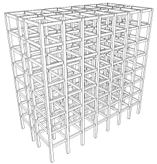
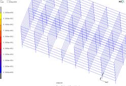
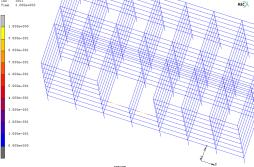
Model A: Frame model with columns and beams
only;
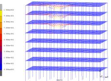
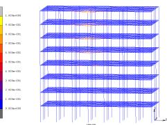
Model B: Frame model including columns, beams
and slabs. When progressive collapse happens, slabs are usually in large deformation
stage, and therefore, the bending bearing capacity of slabs can be ignored
comparing with their suspending capacity. So in this paper, the reinforcement
in slabs is modeled with truss elements to consider the tensile effect of
rebars, and the concrete in slabs is not taken into account. And moreover,
when tensile strain of reinforcement reaches 10%, the reinforcement is considered
to be broken, and then the procedure will delete it automatically. Thus, the
contribution of slabs is conservatively considered by means of this method.
4 Analysis
procedure
4.1 Load case
According to the specification in DoD2005 [2], the following factored load combination is applied
to the entire structures for nonlinear dynamic analyses:
1.2Gk£«0.5Qk£«0.2Wk
(2)
where, Gk =standard value of dead load; Qk =standard
value of live load; Wk =standard value of wind load.
4.2 Analysis
procedure
Alternate Path (AP) method based on the dynamic nonlinear analysis is
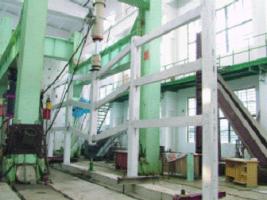
used in this paper to analyze the progressive collapse resistance capacity
because of its high accuracy. In AP method, one vertical load-bearing element
is removed instantaneously from Model A and Model B in every load case to
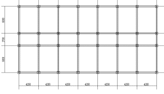
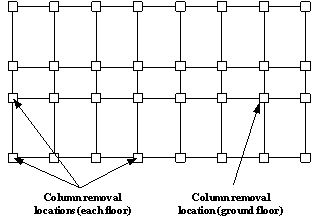
check the bridge over capacity of the residual structures. The columns are
near the middle of the short side, near the middle of the long side and at
the corner of the building at each floor are removed. Besides, an internal
column at ground floor is also removed, as shown in Figure 9.
|
|
|
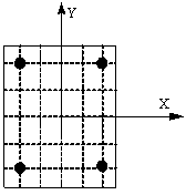
Fig.9 Column removal locations
|
According to the DoD2005
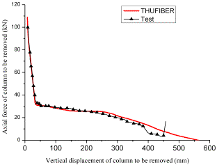
[2], the beams are considered to be failed (or collapsed)
when their deflections reach 10% of their spans or the tensile strain of reinforcement
in them exceeds 10%. If collapse area exceeds the value specified in DoD2005 [2], the structure will be considered that
its progressive collapse resistance is insufficient and the collapsed part
need be strengthened. Both the results of collapse resistance and strengthening
reinforcement of Model A and Model B are compared to analysis the effect of
slabs in collapse process.
5 Results
5.1 Collapse
resistance capacity
The results of simulations
for collapse of Model A and Model B are listed in Table 1. It can be indicated
that Chinese typical RC frames have insufficient collapse resistance. For
the columns in different stories located at the same planar position, the
columns in higher stories have more collapse possibility, as shown in Table
1, because the higher floor the removed column
Table 1 the
results of simulations for collapse of Model A and Model B
|
Floor
|
Column removal location
|
Model A
|
Model B
|
|
ground
|
Corner
|
survive
|
survive
|
|
Long side
|
survive
|
survive
|
|
Short side
|
survive
|
survive
|
|
Internal
|
survive
|
survive
|
|
1 th
|
Corner
|
survive
|
survive
|
|
Long side
|
survive
|
survive
|
|
Short side
|
survive
|
survive
|
|
2 th
|
Corner
|
collapse**
|
survive **
|
|
Long side
|
survive
|
survive
|
|
Short side
|
survive
|
survive
|
|
3 th
|
Corner
|
collapse
|
collapse
|
|
Long side
|
survive
|
survive
|
|
Short side
|
survive
|
survive
|
|
4 th
|
Corner
|
collapse
|
collapse
|
|
Long side
|
collapse **
|
survive **
|
|
Short side
|
survive
|
survive
|
|
5 th¡«7 th
|
Corner
|
collapse
|
collapse
|
|
Long side
|
collapse
|
collapse
|
|
Short side
|
survive
|
survive
|
|