|
5. Theoretical analysis
The
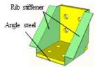
SAS component is a new type of energy-dissipating component. Because Specimen
AR-OUT-S exhibited the highest stability and sufficient strength and initial
stiffness, the SAS component discussed hereafter is similar to Specimen AR-OUT-S.
The yield bending moment of the SAS connection can be calculated by the superposition
of the bending moments provided by the angle steel and the rib stiffener,
respectively. The initial stiffness of the SAS connection can be calculated
through the same superposition method. Note that the design methods of the
angle steel connection have been widely studied by many researchers [38-41].
Therefore, these research outcomes can be used in this work, while the design
method of rib stiffeners needs to be developed.
5.1. Parameter calibration
for the model of angle steel connection
Many
studies have shown that the three-parameter power model proposed by Kishi
and Chen [41] can accurately describe the behavior of angle steel connections
[38-40]. Therefore, the Kishi¨CChen power model was adopted to predict the
moment¨Crotation relations of angle steel connection
in this work. The Kishi¨CChen power model contains three key parameters: initial
stiffness  ,
ultimate moment
,
ultimate moment  ,
and shape parameter
,
and shape parameter
 .
The equation is as follows:
.
The equation is as follows:
| |
|
(1)
|
in
which  ,
M
A and q are moment and relative rotation in the connection, respectively. ,
M
A and q are moment and relative rotation in the connection, respectively.
Kishi and Chen
[41] proposed the computational equations of the initial stiffness
 and the ultimate moment
 . The shape
parameter nA is determined through
the least-squares fitting between the predicted moments and the
experimental ultimate moments. Note that this method can effectively predict
the moment¨Crotation relations when the moment approaches
the ultimate moment. However, the ultimate moment is significantly larger
than the yield moment. The test of Specimen A shows that the moment¨Crotation
relations determined by the
shape parameter nA cannot predict the yield moment well
(Fig. 17). Therefore, to predict the yield moment of the angle steel connection
accurately, the shape parameter was recalibrated in this work by ensuring
that the predicted and experimental moment¨Crotation relations
have same energy within the specified rotation qp, and the new shape parameter is denoted as
. The shape
parameter nA is determined through
the least-squares fitting between the predicted moments and the
experimental ultimate moments. Note that this method can effectively predict
the moment¨Crotation relations when the moment approaches
the ultimate moment. However, the ultimate moment is significantly larger
than the yield moment. The test of Specimen A shows that the moment¨Crotation
relations determined by the
shape parameter nA cannot predict the yield moment well
(Fig. 17). Therefore, to predict the yield moment of the angle steel connection
accurately, the shape parameter was recalibrated in this work by ensuring
that the predicted and experimental moment¨Crotation relations
have same energy within the specified rotation qp, and the new shape parameter is denoted as
 .
.
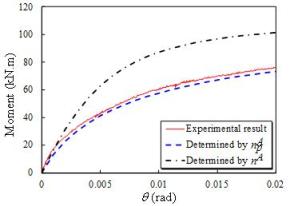
Fig. 17. Differences between nA
and  (neergy with Specimen A)
qp should be greater than the yield rotation, but it should not be
excessively large. Otherwise, it will affect the accuracy of the predicted
yield moment. The maximum acceptable story drift of the steel structure specified
in the Code for Seismic Design of Buildings (GB 50011-2010) [33] is 0.02 rad;
thus, in this work, qp
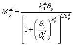
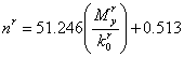
is set to 0.02 rad. Based on the data from literature listed in Table 2,
 can be determined
by least-squares curve fitting (shown in Eq. (2) and Fig. 18).
can be determined
by least-squares curve fitting (shown in Eq. (2) and Fig. 18).
| |
|
(2)
|
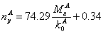
The
yield moment of the angle steel connection MyA
is defined as follows:
| |
|
(3)
|
in which
 is
the yield rotation. is
the yield rotation.
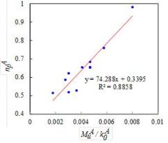
Fig. 18. Least-squares curve fitting of

Table 2
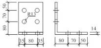
Geometrical and mechanical characteristics of monotonic loading tests
|
Specimen ID
|
Beam (mm)
|
Column (mm)
|
Top angle (seat angle)
(mm)
|

|
|
JT-07 [42]
|
H254´102´5.7´6.8
|
H153´152´5.8´6.8
|
L80´60´8 (L125´75´8)
|
0.622
|
|
JT-08 [42]
|
H254´102´5.7´6.8
|
H153´152´5.8´6.8
|
L80´60´8 (L125´75´8)
|
0.520
|
|
TSC-M [43]
|
H300´150´7.1´10.7
|
H300´150´7.1´10.7
|
L120´120´12
|
0.529
|
|
TA-4 [44]
|
H250´125´6´9
|
H350´175´6´9
|
L140´90´12
|
0.655
|
|
JD1 [45]
|
H300´300´8´12
|
H200´200´12´12
|
L110´110´12
|
0.760
|
|
JD2 [45]
|
H300´300´8´12
|
H200´200´12´12
|
L140´140´16
|
0.982
|
|
W00 [46]
|
H400´200´8´13
|
H408´408´21´21
|
L150´100´12
|
0.516
|
|
ZRBA2-1 [47]
|
H298´149´5.5´8
|
H300´300´10´15
|
L125´125´12
|
0.685
|
|
ZRBA2-2 [47]
|
H298´149´5.5´8
|
H300´300´10´15
|
L125´125´12
|
0.654
|
|
ZRBA2-3 [47]
|
H298´149´5.5´8
|
H300´300´10´15
|
L125´125´12
|
0.656
|
|
F1 [48]
|
H300´250´8´12
|
H400´300´10´14
|
L160´160´10
|
0.587
|
Taking Specimen
A as an example, the comparisons of the predicted moment¨Crotation curves (q ˇÜ 0.02 rad)
determined by nA and  are shown in Fig. 17.
The results show that
are shown in Fig. 17.
The results show that  can better determine
moment¨Crotation relations of angle steel connection when q ˇÜ 0.02 rad.
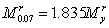
In other words, the yield moment of angle steel connection
can be predicted more accurately by
can better determine
moment¨Crotation relations of angle steel connection when q ˇÜ 0.02 rad.
In other words, the yield moment of angle steel connection
can be predicted more accurately by
 .
.
5.2. Theoretical calculating
method of rib stiffeners
5.2.1. Initial
stiffness provided by rib stiffeners
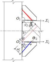
Based on the
FE results, the effective stress area of rib stiffeners can be simplified
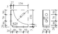
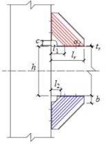
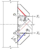
as a set of strips with a specific angle a. Fig. 19(a) shows the equivalent stress
area of rib stiffeners for the calculation of initial stiffness, in which
the red area represents tension and the blue area represents compression. Fig. 19(b) shows the deformation mode of rib stiffeners
with a connection rotation q. Fig. 19(c) shows the deformation of
simplified strips with a connection rotation q. Fig. 19(d)
shows the equivalent force model for the calculation of initial stiffness
provided by rib stiffeners.
|
|
|
|
|
|
(a) Effective stress area
|
(b) Deformation mode of connection
|
(c) Deformation mode of simplified
strips
|
(d) Equivalent force model
|
Fig. 19. Schematics for the calculation of the
initial stiffness provided by the rib stiffeners
(1) For tensile
rib stiffeners:
The strain of
tensile strips is
| |
 , ,
|
(4)
|
where
 is the coefficient accounting for
the nonuniform stress of tensile strips when calculating the initial stiffness,
h is the height of beam, x1 is a variable which is
the distance between the strip and the beam end, a is the inclination angle of strips,
and the recommended value is 45º.
is the coefficient accounting for
the nonuniform stress of tensile strips when calculating the initial stiffness,
h is the height of beam, x1 is a variable which is
the distance between the strip and the beam end, a is the inclination angle of strips,
and the recommended value is 45º.
The cross-sectional
area of tensile strips is
| |
 , ,
|
(5)
|
where tr is the thickness of the rib stiffeners.
The arm of force
of tensile strips to Point O2 is
| |
 . .
|
(6)
|
The moment provided
by a tensile rib stiffener to Point O2 is
|
 , ,
|
(7)
|
where lr is
the height of the rib stiffener, l1 is the minimum distance between the bolt hole edge and
the beam end (Fig. 19), and Er is the modulus of elasticity
of the rib stiffeners.
Consequently,
the initial stiffness provided by a tensile rib stiffener to Point O2
is
|
 . .
|
(8)
|
(2) For compression
rib stiffeners:
The strain of
compression strips is
| |
 , ,
|
(9)
|
where
 is the coefficient accounting for
the nonuniform stress of compression strips when calculating the initial stiffness,
and x2
is a variable that is the distance between the strip and the beam end.
is the coefficient accounting for
the nonuniform stress of compression strips when calculating the initial stiffness,
and x2
is a variable that is the distance between the strip and the beam end.
The cross-sectional
area of the compression strips is
| |
 . .
|
(10)
|
The arm of force
of the compression strips to Point O2 is
| |
 . .
|
(11)
|
The moment provided
by a compression rib stiffener to Point O2 is
|
 , ,
|
(12)
|
where l2 is the distance between the beam end and the
strip closest to the beam end (Fig. 19).
The initial
stiffness provided by a compression rib stiffener to Point O2
is
|
 . .
|
(13)
|
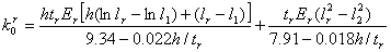
Take a = 45º, the initial stiffness provided
by the rib stiffeners is determined as follows:
|

|
(14)
|
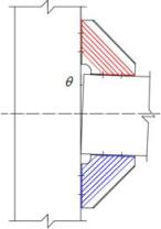
5.2.2. Yield
moment provided by rib stiffeners
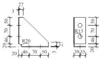
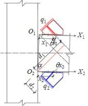
The yield moment
provided by the rib stiffeners can be defined as the sum of the yield moments
provided by all the strips. The corresponding equivalent area, deformation
mode and equivalent force model for the calculation of the yield moment provided
by the rib stiffeners can be determined in Fig. 20(a-d).
|
|
|
|
|
|
(a) Effective stress area
|
(b) Deformation mode of connection
|
(c) Deformation mode of simplified
strips
|
(d) Equivalent force model
|
Fig. 20. Schematics for calculation of yield moment
provided by rib stiffeners
(1) For tensile
rib stiffeners:
The resultant
tensile force is
|
 , ,
|
(15)
|
where b
and c are the dimensions of the rib stiffeners shown in Fig. 20,
 is the yield strength of the rib
stiffeners, and
is the yield strength of the rib
stiffeners, and  is the coefficient accounting for
the nonuniform stress of tensile strips when calculating the yield moment.
is the coefficient accounting for
the nonuniform stress of tensile strips when calculating the yield moment.
The arm of force
of the tensile strips to Point O2 is
|
 , ,
|
(16)
|
The yield moment
provided by a tensile rib stiffener to Point O2 is
|
 . .
|
(17)
|
(2) For compression
rib stiffeners:
The resultant
compression force is
|
 , ,
|
(18)
|
where
 is the coefficient accounting for
the nonuniform stress of compression strips when calculating the yield moment.
is the coefficient accounting for
the nonuniform stress of compression strips when calculating the yield moment.
The arm of force
of compression strips to Point O2 is
|
 . .
|
(19)
|
The yield moment
provided by a compression rib stiffener to Point O2 is
|
 . .
|
(20)
|
Take a = 45º, the yield moment provided
by rib stiffeners is determined as follows:
|

|
(21)
|
|
| |
|
|
|
|
|
|
|
|
|
5.2.3. Coefficients
accounting for nonuniform stress determined by FE models
Based on the
above analysis, the initial stiffness and the yield moment provided by the
rib stiffeners can be calculated, if the coefficients
accounting for nonuniform stress (
 ,
,  ,
,  , and
, and
 )
are determined. Due to the limited number of experiments
available, the FE model calibrated by experimental data (shown in Section
4) is adopted for the parametric analysis herein. To calculate the initial stiffness and yield moment provided by
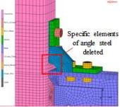
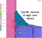
the rib stiffeners and eliminate the influence of angle steel, the specific
elements at the corner of the angle steel in the FE model are deleted (Fig.
21).
)
are determined. Due to the limited number of experiments
available, the FE model calibrated by experimental data (shown in Section
4) is adopted for the parametric analysis herein. To calculate the initial stiffness and yield moment provided by
the rib stiffeners and eliminate the influence of angle steel, the specific
elements at the corner of the angle steel in the FE model are deleted (Fig.
21).
|
|
|
|
|
(a) lr =
0.1 m
|
(a) lr =
0.15 m
|
(a) lr =
0.2 m
|
Fig.
21.
FE models with different height of rib stiffeners
The variable
parameters in the FE model include the height of beam h
(0.3, 0.35, and 0.4 m), the thickness of rib stiffeners tr
(0.001, 0.002, 0.003, 0.004, 0.005, 0.006, and 0.007 m), the height
of rib stiffeners lr (0.1, 0.15, and 0.2 m),
and the yield strength of rib stiffeners
 (235,
345, and 368 MPa). The definition of the
variable parameters (h, tr,
and lr) are shown in Fig. 19(a). The FE models with different heights of rib stiffeners are
shown in Fig. 21. The simulation results show that if tr/ta
(ta is the thickness of the angle steel) is too large,
it will result in the deformation of the angle steel, which will reduce the
energy-dissipating capacity. In contrast, if tr/ta
is too small, the rib stiffeners have little contribution. Consequently, after
a series of parametric discussions, tr/ta
should meet the following criterion:
(235,
345, and 368 MPa). The definition of the
variable parameters (h, tr,
and lr) are shown in Fig. 19(a). The FE models with different heights of rib stiffeners are
shown in Fig. 21. The simulation results show that if tr/ta
(ta is the thickness of the angle steel) is too large,
it will result in the deformation of the angle steel, which will reduce the
energy-dissipating capacity. In contrast, if tr/ta
is too small, the rib stiffeners have little contribution. Consequently, after
a series of parametric discussions, tr/ta
should meet the following criterion:
 .
.
With the comparisons of initial stiffness and yield moment between
the simulation results and the computational results from Eqs. (14) and (21),
 ,
,
 ,
,
 , and
, and
 can be determined as follows by data fitting:
Substituting
 ,
,
 ,
,
 ,
and
,
and  into Eqs.
(14) and (21) results in
into Eqs.
(14) and (21) results in
|
 and and
|
(25)
|
|
 . .
|
(26)
|
The comparisons
of the initial stiffness and yield moment between the FE results and the calculation
results from Eqs. (25) and (26) are shown in Figs. 22 and 23, respectively,
and the results show good agreement.
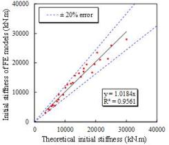
Fig.
22. Initial stiffness
provided by rib stiffeners
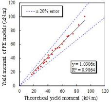
Fig.
23. Yield moment
provided by rib stiffeners
Additionally, the moment-rotation relations provided by rib stiffeners
can be defined as follows, similar to Eq. (1):
| |
 , ,
|
(27)
|
where  ,
,
 is the maximum moment
provided by rib stiffeners when
is the maximum moment
provided by rib stiffeners when  , and
, and  is the shape parameter of
the rib stiffeners.
is the shape parameter of
the rib stiffeners.
Because the strength provided
by some rib stiffeners will decrease when  ,
,
 is taken as a basic
parameter in this work. Based on the former mentioned FE results (Figs. 24
and 25) and Eqs. (25) and (26),
is taken as a basic
parameter in this work. Based on the former mentioned FE results (Figs. 24
and 25) and Eqs. (25) and (26),  and
and
 can be determined as follows:
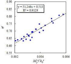
Fig.
24. Data fitting
for 
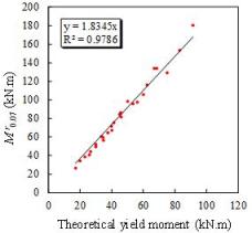
Fig.
25. Theoretical
calculation of 
| |
 and and
|
(28)
|
| |
 . .
|
(29)
|
Consequently,
 can be determined as
follows:
can be determined as
follows:
| |
|
(30)
|
5.3. Evaluation of initial
stiffness and yield moment provided by SAS
Based on the above analysis, the calculation method of the initial
stiffness and the yield moment provided by SAS can be determined as follows:
The initial stiffness provided
by SAS is the sum of that provided by the angle steels and the rib stiffeners:
|

|
(31)
|
Note that the stiffness of SAS will significantly decrease after
the yield of the rib stiffeners. Therefore, it is assumed that SAS will reach
the yield point when the rib stiffeners yield, and, consequently, the yield
moment provided by SAS can be determined as follows: (1) determine the yield
moment provided by the rib stiffeners  through Eq. (26); (2)
determine the yield rotation
through Eq. (26); (2)
determine the yield rotation  of the rib
stiffeners through Eq. (30); and (3) determine the yield moment provided by the angle steel
of the rib
stiffeners through Eq. (30); and (3) determine the yield moment provided by the angle steel
 through Eq. (3). Subsequently,
the yield moment provided by SAS can be determined as follows:
through Eq. (3). Subsequently,
the yield moment provided by SAS can be determined as follows:
|
|
(32)
|
To validate
the above equation, a series of FE models of SAS were established, and the
variable parameters in the FE models included the following: the thickness
of the angle steel ta = 14 mm; the other parameters of angle
steels, the same as the FE model shown in Fig. 14(a); the height of beam h
(0.3, 0.35, and 0.4 m); the thickness of rib stiffeners tr
(0.002, 0.003, and 0.004 m); and the height of rib stiffeners lr
(0.1, 0.15, and 0.2 m). The comparisons of the initial stiffness and
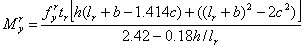
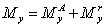
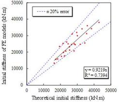
the yield moment provided by SAS between the simulation results and the calculation
results from Eqs. (31) and (32) are shown in Fig. 26 and Table 3, with
a good agreement, which proves the rationality of the calculation method proposed
in this work.
|
|
|
|
(a) Initial stiffness
|
(b) Yield moment
|
Fig.
26. Comparisons of initial stiffness
and yield moment provided by SAS between simulation and calculation results
Table 3
Comparisons of initial stiffness
and yield moment provided by SAS between the FE results and the proposed model
|
No.
|
h
(mm)
|
tr (mm)
|
lr
(mm)
|
Initial stiffness
|
Yield moment
|
|
FE results
(kNˇ¤m)
|
Eq. (31)
(kNˇ¤m)
|
Error
|
FE results
(kN)
|
Eq. (32)
(kN)
|
Error
|
|
1
|
300
|
2
|
100
|
1.34ˇÁ104
|
1.63ˇÁ104
|
21.4%
|
77.90
|
79.68
|
2.28%
|
|
2
|
300
|
3
|
100
|
1.57ˇÁ104
|
1.73ˇÁ104
|
10.2%
|
80.20
|
89.08
|
11.07%
|
|
3
|
300
|
4
|
100
|
1.59ˇÁ104
|
1.84ˇÁ104
|
15.4%
|
88.90
|
98.08
|
10.33%
|
|
4
|
300
|
2
|
150
|
2.34ˇÁ104
|
1.94ˇÁ104
|
-17.1%
|
94.40
|
87.07
|
-7.76%
|
|
5
|
300
|
3
|
150
|
2.53ˇÁ104
|
2.15ˇÁ104
|
-14.8%
|
99.00
|
101.33
|
2.35%
|
|
6
|
300
|
4
|
150
|
2.62ˇÁ104
|
2.37ˇÁ104
|
-9.4%
|
111.70
|
115.05
|
3.00%
|
|
7
|
300
|
2
|
200
|
1.78ˇÁ104
|
2.24ˇÁ104
|
25.8%
|
95.00
|
97.50
|
2.63%
|
|
8
|
300
|
3
|
200
|
2.13ˇÁ104
|
2.55ˇÁ104
|
19.7%
|
118.30
|
117.25
|
-0.89%
|
|
9
|
300
|
4
|
200
|
2.45ˇÁ104
|
2.88ˇÁ104
|
17.4%
|
128.90
|
136.43
|
5.84%
|
|
10
|
350
|
2
|
100
|
1.74ˇÁ104
|
2.07ˇÁ104
|
18.5%
|
90.80
|
88.46
|
-2.58%
|
|
11
|
350
|
3
|
100
|
1.99ˇÁ104
|
2.19ˇÁ104
|
9.9%
|
95.90
|
99.54
|
3.80%
|
|
12
|
350
|
4
|
100
|
2.07ˇÁ104
|
2.32ˇÁ104
|
12.1%
|
105.80
|
110.00
|
3.97%
|
|
13
|
350
|
2
|
150
|
2.50ˇÁ104
|
2.46ˇÁ104
|
-1.9%
|
99.60
|
95.86
|
-3.76%
|
|
14
|
350
|
3
|
150
|
3.11ˇÁ104
|
2.70ˇÁ104
|
-13.1%
|
115.50
|
112.27
|
-2.79%
|
|
15
|
350
|
4
|
150
|
3.20ˇÁ104
|
2.97ˇÁ104
|
-7.2%
|
130.70
|
127.82
|
-2.21%
|
|
16
|
350
|
2
|
200
|
2.08ˇÁ104
|
2.82ˇÁ104
|
35.4%
|
110.00
|
106.86
|
-2.85%
|
|
17
|
350
|
3
|
200
|
2.48ˇÁ104
|
3.18ˇÁ104
|
28.3%
|
129.30
|
129.15
|
-0.11%
|
|
18
|
350
|
4
|
200
|
3.13ˇÁ104
|
3.56ˇÁ104
|
14.0%
|
149.70
|
150.51
|
0.54%
|
|
19
|
400
|
2
|
100
|
2.32ˇÁ104
|
2.53ˇÁ104
|
8.9%
|
103.50
|
97.09
|
-6.20%
|
|
20
|
400
|
3
|
100
|
2.47ˇÁ104
|
2.67ˇÁ104
|
8.2%
|
111.10
|
110.15
|
-0.85%
|
|
21
|
400
|
4
|
100
|
2.51ˇÁ104
|
2.82ˇÁ104
|
12.6%
|
123.10
|
122.26
|
-0.68%
|
|
22
|
400
|
2
|
150
|
3.00ˇÁ104
|
3.01ˇÁ104
|
0.4%
|
112.30
|
104.22
|
-7.20%
|
|
23
|
400
|
3
|
150
|
3.41ˇÁ104
|
3.29ˇÁ104
|
-3.6%
|
130.40
|
123.12
|
-5.58%
|
|
24
|
400
|
4
|
150
|
3.61ˇÁ104
|
3.60ˇÁ104
|
-0.2%
|
150.00
|
140.65
|
-6.23%
|
|
25
|
400
|
2
|
200
|
2.56ˇÁ104
|
3.45ˇÁ104
|
34.5%
|
122.50
|
115.72
|
-5.53%
|
|
26
|
400
|
3
|
200
|
3.42ˇÁ104
|
3.85ˇÁ104
|
12.4%
|
145.50
|
140.87
|
-3.18%
|
|
27
|
400
|
4
|
200
|
3.80ˇÁ104
|
4.30ˇÁ104
|
13.1%
|
167.90
|
164.57
|
-1.98%
|
|
Average error
|
9.3%
|
|
|
-0.54%
|
|
Standard deviation
|
0.143
|
|
|
0.048
|
|