|
INTRODUCTION
Fire is one of the most dangerous disasters
that can destroy buildings. With the occurring of local damage or even complete collapse of buildings under fire,
more and more attentions are paid to the security of structures under fire
[1, 2]. As a result, many theoretical and experimental researches have been conducted on the behaviors of various structural
elements, substructures and
even whole structures under fire [3]. Traditional researches of structure under
fire are based on single element test in the standard furnace. In
the 1980's and the 1990's, performance based conception for fire design is
adopted by BS5950 Part 8 and EC4[4] respectively in UK and Europe, which means the safety of a certain
structure in fire can be determined with the fire resistant calculation.
In China, the current codes including the fire safety code for building design
and the code for fire protection design of tall buildings are still based on
single element test in standard fire. With the improving requirements on disaster
resistance of building structures, the performance-based fire resistant design method has drawn great attention
[5], which requires the whole
structural analysis for real fire situation. Due to the extreme large workload in the complex building simulations
with solid finite elements, it is necessary to develop a suitable finite element model to study the
failure process of the structural elements exposed to fire. Now,
fiber beam model is widely used in reinforced concrete
(RC) structures. Hence, a novel numerical model based on the fiber beam model
is proposed in this paper to simulate the collapse of reinforced concrete beam
and column under fire.
The model of fiber beam developed here is a
two nodal element with six degrees of freedom at each
node and the cross section of beam element is
divided into many small concrete and steel fibers. The non-uniform stiffness
of cross section along the beam, which is caused by the various kinds of loads
and the degradation of materials at elevated temperatures, is considered with
the 3-point Gauss integration along the axis of each fiber. Geometric nonlinearity
of large displacement is also modeled with Total
Lagrangian (TL) description, and the explicit tangential stiffness
matrix is deduced for proposed fiber beam with the consideration of large displacements.
By applying the incremental thermo elastic-plastic constitutive model, the incremental
equilibrium equations are also established for the element of fiber beam. Finally,
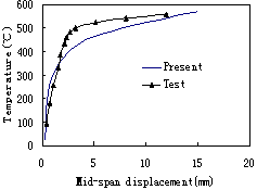
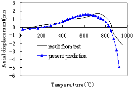
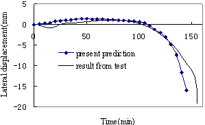
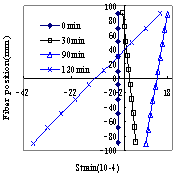
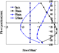
the analyzing results are compared with the data from fire experiments. The
results show that the predictions of the model proposed in this paper agree
well with the results of the tests and can be used to analyze and simulate the
collapse of reinforced concrete elements under fire.
THE ELEMENT MODEL OF FIBER BEAM
The fiber beam element consists of two nodes
and six degrees of freedom at
each node, as shown in Fig.1. The cross section of beam element is divided into
many small concrete and steel fibers and the following assumptions are established:
1) Geometric nonlinearity due to large displacement
is considered but the strain of material is still treated as small strain situation.
2) Plane-in-plane assumption is adopted to constraint
the deformation of different fibers in the same section. 3) For each fiber only the longitudinal stress is considered. 4) The material of each fiber may be different,
and the 3-point Gauss integration is considered along the axis of each fiber.3)
Each fiber within the cross-section can have a different temperature, but this
is uniform along the fiber.
The deformation of the fiber beam element
is based on the Total Lagrangian (TL) method, and the displacements at any point
on the reference axis between two end nodes can be expressed as follows:
 (1)
(1)
where 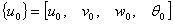 are
the displacements at any point. are
the displacements at any point.
 is
the shape function matrix given by Bathe [6]. is
the shape function matrix given by Bathe [6].
 is
the nodal displacement vector. is
the nodal displacement vector.
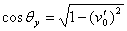
The displacements of any point A on any cross-section
can be expressed as
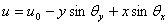 (2-a)
(2-a)
 (2-b)
(2-b)
 (2-c) (2-c)
where  , ,
 are the
coordinates of point A. are the
coordinates of point A.
It can be seen from Fig.3 and Fig.4 that
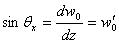 and and
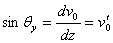 (3-a) (3-a)
then 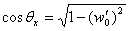 and and
 (3-b) (3-b)
if  and and
 (3-c) (3-c)
then the displacements of any point A
can be expressed as
 (4-a)
(4-a)
 (4-b)
(4-b)
 (4-c)
(4-c)
 (4-d)
(4-d)
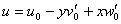
|
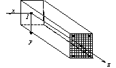
Fig.1: The fiber beam element
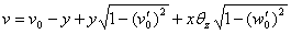
|
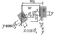
Fig.2: Element
cross-section mesh
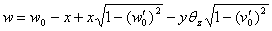
|
|
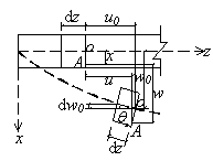
Fig.3: Deformations in plane xz
|
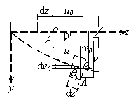
Fig.4: Deformations in plane yz
|
For each fiber only the longitudinal
stress is considered,
the stain of point A can be expressed
as
 (5)
(5)
and  (6-a) (6-a)
 (6-b) (6-b)
where  represents
the small linear-displacement strains and represents
the small linear-displacement strains and
 represents
the non-linear displacement stains. represents
the non-linear displacement stains.
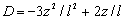
then  (7) (7)
 (8)
(8)
where  , ,
 , ,
 , ,
 Ł¬ Ł¬  , ,
 , ,
 , ,
 Ł¬ Ł¬ 
then  can be
expressed as can be
expressed as
 (9)
(9)
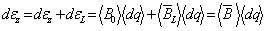
On the other hand, the total thermo elastic-plastic
strain increment in each fiber can be expressed as
 = =
 + +
 + +
 + +
 + +
 (10)
(10)
where  =incremental
elastic strain components, =incremental
elastic strain components,
 =incremental
strain components due to temperature dependent material properties, =incremental
strain components due to temperature dependent material properties,  =incremental
thermal strain components, =incremental
thermal strain components,  =
incremental plastic strain components. =
incremental plastic strain components.
When the isotropic hardening scheme is
considered, the thermo elastic plastic constitutive equation can be expressed
by [7]
 = =
 Ł¨ Ł¨  - -

 - -


 - -
 - -

 Ł©
(11) Ł©
(11)
where  is
thermo elastic plastic constitutive matrix, is
thermo elastic plastic constitutive matrix,  is the
thermal expansion coefficient, is the
thermal expansion coefficient,
 = =
 Ł¬ Ł¬  = =
 Ł¬ Ł¬  = =
 - -
 and and
 = =


 T T
 / /

Because only the longitudinal strain
is considered for each fiber in the element, then
 = =
 , ,
 = =
 , ,
 , ,
 , ,
 , ,
where  is
the axial stress of the fiber at the gauss point, is
the axial stress of the fiber at the gauss point,  is the
tangential stiffness of the fiber at the gauss point is the
tangential stiffness of the fiber at the gauss point
If  = =
 - -
 ,and ,and
 =- =-
 Ł¬ Ł¬  = =
 (12)
(12)
then
 = =
 = =
 (13)
(13)
where  is the
total incremental thermo mechanical strain, is the
total incremental thermo mechanical strain,  is the
total incremental strain, is the
total incremental strain,
 = =

 - -


 + +


 is the
incremental thermal strain. is the
incremental thermal strain.
Finally, the tangential stiffness matrix
of the fiber beam can be deduced with the deformation equations and the thermo
elastic plastic constitutive equation. The incremental strain energy in the
element can be expressed as
 =1/2 =1/2


=  (14)
(14)
The work done on the element by the extern
force is
 =- =-

 (15)
(15)
|