Floor Acceleration Control of Super-Tall Buildings with Vibration Reduction Substructures

Lei Zhang1, Xinzheng Lu2, *, Hong Guan3, Linlin Xie1, and Xiao Lu4

1 Beijing Engineering Research Center of Steel and Concrete Composite Structures, Tsinghua University, Beijing, China

2 Key Laboratory of Civil Engineering Safety and Durability of China Education Ministry, Department of Civil Engineering, Tsinghua University, Beijing, China

3 Griffith School of Engineering, Griffith University Gold Coast Campus, Queensland 4222, Australia

4 Department of Civil Engineering, Beijing Jiaotong University, Beijing, China

The Structural Design of Tall and Special Buildings,
Accepted on Oct. 10, 2016. DOI: 10.1002/tal.1343.

SUMMARY

When a super-tall building is subjected to service level earthquakes (SLEs) or design basis earthquakes (DBEs), its excessive floor acceleration due to the acceleration amplification effect can lead to unacceptable economic loss and functional interruption. This work aims to design the top stories of super-tall buildings in a form of a vibration reduction substructure (VRS) (acting as a giant TMD with a large mass ratio) to control the floor acceleration of the building subjected to SLEs and DBEs. A simplified analytical model for 300 m super-tall buildings is developed based on the flexural-shear coupling beam model. Using the simplified model with a VRS on the top of the building, the floor acceleration reduction effect of the VRS is studied through time history analysis under actual ground motions. The optimal frequency of the VRS to reduce the floor acceleration is determined through parametric discussion, and the feasibility of using the VRS for different layouts of super-tall buildings is validated. The outcome of this study is expected to provide some references for engineering design to mitigate vibration of super-tall buildings.

KEY WORDS: super-tall building, vibration reduction substructure, floor acceleration, optimal frequency, flexural-shear coupling beam model, earthquake

If you need the PDF version of this paper, please email to luxinzheng@sina.com


1 Introduction

With the rapid development of urbanization, super-tall buildings have been widely constructed throughout the world. The seismic resilience of super-tall buildings has significant impact on the society, which requires the buildings to be safe under strong earthquakes, and the economic loss and function interruption to be kept to a minimum after small or moderate earthquakes. Extensive research development in earthquake engineering has indeed greatly improved the collapse resistance of super-tall buildings. Existing literature has confirmed that super-tall buildings in general are designed to have enough safety margins when subjected to the maximal considered earthquakes (MCEs) (Lu et al., 2011; Lu et al., 2013b; Lu et al., 2015). However, when subjected to service level earthquakes (SLEs) or design basis earthquakes (DBEs), the floor acceleration of the upper part of super-tall buildings as a result of the acceleration amplification effect (Chen et al., 2013a) may exceed six times the peak ground acceleration (PGA). Excessive floor acceleration can lead to damage of the building contents and many non-structural components. Such a damage will not only result in severe economic losses but also deter the normal function of the building (Shome et al., 2013; Tian et al., 2016). Therefore, proposing an engineering solution that can reduce the floor acceleration of super-tall buildings under SLEs and DBEs is critically important.

Three types of vibration reduction devices are commonly used in building structures: (1) energy dissipation devices, (2) base isolation devices, and (3) dynamic vibration absorbers (e.g. tuned mass dampers (TMDs), tuned liquid dampers (TLDs) and tuned liquid column dampers (TLCDs)). With respect to the plastic energy dissipation devices, their energy dissipation capacities are not fully utilized (Vafaei and Eskandari, 2015; Piedrafita et al., 2015) when the building is subjected to SLEs, because they still exhibit the elastic behavior. Although base isolation devices can be effective, their limited scope does not cover their application to super-tall buildings. Therefore, TMD, as a type of widely used efficient passive control device, is a feasible choice for reducing the floor acceleration of super-tall buildings subjected to SLEs and DBEs. Note that TMDs have already been widely and successfully used to reduce wind-induced vibration of buildings (Liu et al., 2008; Aly, 2014; Zhou et al., 2015)

Previous studies have demonstrated that TMDs can reduce the seismic floor acceleration of super-tall buildings (Zhang et al., 2015). Therefore, how to optimize the parameters of TMDs (e.g., the natural frequency, the mass and the damping ratio) to achieve a best vibration effect subjected to constrained budget is a key challenge. Single degree-of-freedom (SDOF) systems have been used by many researchers (e.g., Sadek et al. (1997), Krenk and Høgsberg (2008), Cheung and Wong (2011), Xiang and Nishitani (2015)) to study the parameter optimization of TMDs. However, SDOF systems are clearly unsuitable for super-tall buildings. Marano et al. (2007) and Ozsariyildiz and Bozer (2015) adopted multiple degrees-of-freedom (MDOF) systems with a limited number of degrees-of-freedom (DOF ≤ 10) to study the vibration reduction effect of TMDs. Such models are suitable for deformation control because the structural deformation is mainly governed by the lower-order vibration modes. The floor acceleration of super-tall buildings, on the other hand, is affected by the higher-order vibration modes, which cannot be fully represented by a system having limited degrees-of-freedom. In addition, most existing studies adopted harmonic excitation (Hartog and Pieter, 1956; Bekdaş and Nigdeli, 2011) or white noise excitation (Bakre and Jangid, 2007; Angelis et al., 2012; Rüdinger, 2014) as ground motion input instead of the actual seismic ground motion. Such a simplification can reduce the influence of the randomness of ground motions. However, it cannot accurately reflect the actual response of the structure during earthquakes.

Most importantly, existing research has proven that the vibration reduction effect can be improved with the increase of the mass of the TMD, on the condition that the vibration period of the TMD is already optimized. Given the cost and complexity associated with installation, the TMDs with a small mass ratio m (i.e., between 0.5% and 2%, m = m/M, where m is the mass of the TMD and M is the mass of the building) have been installed in the existing super-tall buildings. Such a small mass ratio restricts the TMD to be fully effective. Therefore, how to design a TMD with sufficient mass ratio is a critical challenge for vibration reduction of super-tall buildings. Chulahwat (2015) proposed a hybrid floor slab TMD and isolation system for vibration control with no additional mass, whereby the floor slabs are allowed to move relative to the main frame. Hoang et al. (2008) considered bridge decks and the isolation system together as a giant TMD to reduce the seismic force of the bridge, and proved that a TMD with a large mass ratio is effective in minimizing the structural response and is robust to the uncertainties of the parameters (e.g., the excitation frequency and the natural frequencies of the structure). Chai and Feng (1997) and Lan et al. (2004) proposed to install seismic isolators and dampers between the main frames and the sub-frames of mega-frame buildings, through which the sub-frames can be regarded as a series of small vibration reduction substructures (VRSs). With the total mass of the VRSs being much greater than that of the conventional TMD, the vibration reduction effect becomes far significant.

Given the above background, this work aims to design the top stories of super-tall buildings to function as a VRS (acting as a giant TMD with a great mass ratio) to control their floor acceleration subjected to SLEs and DBEs. A simplified analytical model based on the flexural-shear coupling beam model is developed for 300 m super-tall buildings. Using the simplified model with a VRS on the top of the building, the floor acceleration reduction effect of the VRS is studied through time history analysis under actual ground motions. The optimal frequency of VRS to reduce the floor acceleration is determined through parametric discussion, and the feasibility of this method for different layouts of super-tall buildings is validated. The outcome of this study is expected to provide reference for the engineering design to mitigate vibration of super-tall buildings.

2 Concept of the VRS

In 1995, Feng and Mita (1995) for the first time proposed an innovative vibration control system, a mega-substructure configuration composed of a main structure to resist loads and some substructures acting as giant TMDs. Thereafter, many studies on the vibration control of mega-substructures have been performed, and new forms of mega-substructure systems have been proposed, including the multifunctional vibration absorption reinforced concrete (RC) mega-frame structures (Lan et al., 2000), the passive mega-sub controlled structures (Zhang et al., 2009; Limazie et al., 2013), and the vibration absorption RC mega-frame suspension systems (Wang et al., 2008). Currently, mega structure systems, such as mega-frame systems (Jiang et al., 2014) and mega column-core tube-outrigger truss systems (Lu et al., 2011), are widely adopted in super-tall buildings due to their high lateral stiffness and flexible layout. The main structure of these systems commonly consists of mega columns (or corner tubes), strengthened stories, core tubes and outrigger trusses, which are able to resist most of the vertical and horizontal loads. In contrast, the secondary frames or sub-frames, regarded as substructures and supported by the main structure, have little contribution to the structural lateral stiffness (Lu et al., 2014; Lu et al., 2016). Consequently, both mega-frame systems and mega column-core tube-outrigger truss systems have a clear definition to distinguish the main structures and the substructures. For this reason, some top stories of the substructures can be designed as a VRS, and its vertical load is transferred to the main structure. For example, the design schemes of the VRS installed in a super-tall mega-frame and a super-tall mega column-core tube-outrigger building are shown in Figure 1a and Figure 1b, respectively. For a 300 m super-tall building, the mass ratio of the VRS consisting of several stories of the substructures at the top of the building can easily reach 5%, which is an ideal value for effective TMD vibration control. Therefore, it is more feasible to achieve a satisfactory vibration reduction effect using the VRS with a large mass ratio. Dampers or other energy dissipation devices can be placed in the connections between the main structure and the substructure to control the damping ratio and the frequency of the VRS. Such dampers have the ability to dissipate energy, reduce vibration of the structure and prevent unnecessary damage caused by collisions between the main structure and the substructure.

Figure 1 Design scheme of VRS in typical super-tall buildings

Figure 1 Design scheme of VRS in typical super-tall buildings

(a) Super-tall mega-frame with VRS

(b) Super-tall mega column-core tube-outrigger building with VRS

Figure 1 Design scheme of VRS in typical super-tall buildings

The vibration reduction effect of VRSs has been confirmed by Lan et al. (2000) and Wang et al. (2008) through analytical studies and shaking table tests. Zhang et al. (2009), Limazie et al. (2013) and Tan et al. (2014) further discussed parameter optimizations for the VRSs. Nevertheless, most existing research has primarily focused on multi-story buildings and tall buildings of vibration period less than 1.5 s and their seismic responses are largely controlled by the lower-order vibration modes. In addition, the VRSs being investigated to date have mainly functioned to reduce the deformation of the buildings. As a consequence, studies related to the VRS for floor acceleration control of super-tall buildings with vibration period longer than 5 s have not been reported in the literature. Given that higher-order vibration is critical for floor acceleration control and seismic responses of super-tall buildings, in-depth research is thus highly desirable.

3. Analytical model of 300 m super-tall buildings and

 ground motion records

3.1 Flexural-shear coupling beam model and parameter selection

According to the Council on Tall Buildings and Urban Habitat (CTBUH), buildings higher than 300 m are classified as super-tall buildings. The statistics reported by the CTBUH also shows that currently the largest proportion of super-tall buildings is around the height of 300 m. Given that real engineering application of super-tall buildings with VRS is non-existence, future application of such structural system will be initiated from a relatively regular structure. Thus, super-tall buildings with a height of 300 m are considered in this work. Note that this work aims at investigating the structural behavior with generality instead of focusing on a particular building, thus the values of parameters of the super-tall buildings (e.g., self-weight, vibration period, mass/stiffness distribution) should be representative and cover a broad range of common engineering practices.

The structural components in a super-tall building are extensive, making the computational load of a refined finite element (FE) model of such a structure unacceptable for a large number of parametric studies. Therefore, the Miranda and Taghavi’s (2005) equivalent continuum model consisting of a flexural and a shear cantilever beam (referred to as the “flexural-shear coupling beam model” hereafter) is selected in this work to establish the simplified model of the super-tall building. This model is able to efficiently simulate the seismic response of super-tall buildings with satisfactory accuracy, which has been substantiated by Lu et al. (2013a) and many other researchers. The schematic of this model is shown in Figure 2, where the flexural and shear cantilever beams are connected by an infinite number of axially arranged rigid links to achieve lateral deformation compatibility at the same story height. The response of this continuum model, subject to a horizontal ground motion acceleration, is given by the following partial differential equation:


(1)

where r (x) denotes the mass per unit length in the model, u(x, t) is the lateral displacement at a non-dimensional height x at time t, x varies between 0 at the base of the building and 1 at the roof level, H is the total height of the building, ug(t) is the acceleration history of the ground motion, and EI(x) and GA(x) are the flexural stiffness of the flexural beam and the shear stiffness of the shear beam along the structural height, respectively. Miranda and Taghavi (2005) assumed that the variations in the shear and flexural stiffnesses along the height are identical, and such a variation of the simplified model is denoted by S(x). Therefore, EI(x) and GA(x) can be expressed by the following equations:


EI(x)=EI0·S(x)

(2)


GA(x)=GA0·S(x)

(3)

where EI0 and GA0 denote the flexural and shear stiffnesses at the base of the model, respectively. The dimensionless parameter a=H(GA0/EI0) 1/2 controls the proportions of the flexural and shear deformations in the simplified model, namely, the lateral deformation pattern of the building. When the values of the abovementioned four fundamental parameters (r(x), S(x), EI0 and a) are given, the seismic response can be predicted by the simplified model through time history analysis. Note that EI0 can be determined by fundamental period (T1). As T1 is commonly used by engineers, T1 is thus selected as one of the four fundamental parameters instead of EI0 for the following parametric studies. Based on the fact that for buildings with a height of 300 m, T1 is normally in the range of 5~6 s (Xu et al., 2014), a series of models with different T1 (i.e., T1 = 4, 5, 6 and 7 s) are subsequently developed to discuss the influence of T1 on the dynamic behavior of the super-tall buildings with VRS.

Figure 2 The flexural-shear coupling beam model

Figure 2 The flexural-shear coupling beam model

Further, Miranda and Taghavi (2005) concluded that the dimensionless parameter a has a strong influence on the dynamic characteristics of the structure. Therefore, different a  values of 1.0, 1.5 and 2.0 are discussed in this work. Such a range of a values provides a practical coverage for super-tall buildings.

Based on the statistical data of CTBUH (http://skyscrapercenter.com/buildings), the total floor area of super-tall buildings with a height of approximately 300 m ranges from 11,000 to 17,000 square meters. According to the National Technical Measures for Design of Civil Construction: Structure (MOHURD, 2009), the typical dead load of tall RC buildings is approximately 14-16 kN/m2, and the typical floor live load is approximately 2-4 kN/m2. Thus, the mass of a 300 m super-tall building can be estimated to range from 165,000 to 306,000 tons. Accordingly, the mass of the building is set to 200,000 tons in this work.

       It is well recognized that the mass and stiffness of most super-tall buildings are gradually reduced along the structural height. Miranda and Taghavi (2005) found that for most multi-story and tall buildings, the variation of the mass of the flexural-shear coupling beam model along the structural height has little influence on the dynamic characteristics of the structure. In addition, Miranda and Taghavi (2005) also found that a linear or a parabolic stiffness distribution has little influence on the dynamic characteristics of the structure under the condition that the stiffness ratio lSRTB (calculated by the ratio of the top story stiffness to the bottom story stiffness) is a fixed value. Therefore, in this work, a linear distribution is adopted to describe the mass distribution pattern of the flexural-shear coupling beam model, and a parabolic distribution is adopted for the stiffness distribution pattern, according to Lu et al. (2013a). Furthermore, the structural information of more than 30 tall and super-tall buildings with heights in the range of 200-600 m is collected and analyzed in this work (Xu et al., 2002; Wang et al., 2004; Guo, 2005; Zhou and Li, 2006; Yan et al., 2007; Fu et al., 2008; Zhu, 2008; Qi et al., 2010; Gong and Zhang, 2011; Huang et al., 2011; Chen et al., 2012; Liu et al., 2012; Wang et al., 2012; Wang, 2012; Zhu and Lu, 2012; Chen et al., 2013b; Han et al., 2013; Li et al., 2013; Qiu et al., 2013; Sun et al., 2013; Wu et al., 2013; Yang et al., 2013; Bu and Guo, 2014; Liu et al., 2014; Wang and Zhao, 2014; Wang et al., 2014; Feng et al., 2015; Ha et al., 2015a; Ha et al., 2015b; Yu et al., 2015). The ratio of the top story mass to the bottom story mass of the buildings (referred to as lMRTB hereafter) is in the range of 0.25-0.5, and lSRTB is in the range of 0.2-0.6. Thus, lMRTB and lSRTB are set to 0.25 and 0.28, respectively, for the flexural-shear coupling beam model. The influence of different lMRTB and lSRTB values will be discussed in Section 6, which shows little impact on the optimized vibration reduction effect.

A 2.5% structural damping ratio of super-tall buildings subjected to SLEs and DBEs is adopted following the recommendation of the TBI Guidelines (PEER, 2010).

Consequently, analysis results of 12 flexural-shear coupling beam models of the 300 m super-tall buildings are discussed, including 4 different T1 values and 3 different a values.

3.2 Parameters associated with the VRSs

In this work, the secondary frames or sub-frames of some top stories can be designed as the VRS at the top of the main structure like a huge TMD, which is simulated as a mass block connected to the top floor of the flexural-shear coupling beam model through a spring element with equivalent damping and stiffness characteristics.

Floor acceleration reduction provided by the VRS is affected by its own mass m, damping ratio x and natural frequency f. The reduction is also influenced by the number and position of the VRS. Considering that the acceleration response at the top stories is usually the largest, a single VRS is thus installed at the top of the building for ease of construction. Due to the limitation of the cost and structural bearing capacity, the mass ratio of the conventional TMD fitted in super-tall buildings is rarely greater than 2%. For example, the mass ratio of the TMD installed in Shanghai Tower is less than 0.2%. Zuo and Nayfeh (2005) found that a TMD with a large mass ratio can effectively reduce the floor displacement. However, when the mass ratio is greater than 5%, the floor displacement reduction is not be as significant with a further increase of this ratio. Therefore, to provide a practical coverage for the VRS, mass ratios of the VRS ranging from 0.1% to 10% are studied in this work. Note that the VRS and the main structure can be connected with the dampers (Lan et al., 2000), and the corresponding damping ratios in the range of 5%-40% are found by Landi et al. (2014). Such a range is also employed in this work. Based on the optimal frequency of the VRS in reducing the floor acceleration as suggested by the authors (Zhang et al., 2015), this work intends to cover the frequency range of 0.1~10 Hz. As described above, the mass ratios, damping ratios and frequencies of the VRS are considered to cover the potential scenarios of engineering practice.

3.3 Ground motion records

To fully consider the random nature of ground motions, 22 far-field ground motion records recommended by FEMA-P695 (FEMA, 2009) are used as input in this study. As the response of the super-tall building is discussed under SLEs and DBEs, the PGA of the ground motions is adjusted to 0.1 g (g=9.8 m/s2), which is the PGA of DBEs (i.e., 10% probability of exceedance in 50 years) of the 7-degree design intensity as recommended in the Code for Seismic Design of Buildings (GB50011-2010) (MOHURD, 2010). Due to the large safety margin set for super-tall buildings, the main structures of the super-tall buildings in general behave in the elastic stage subjected to SLEs and DBEs (Lu et al., 2014; Lu et al., 2016). Therefore, elastic time history analysis is performed to evaluate the seismic response of the super-tall building.

4. Floor acceleration reduction effect of VRS

For the clarity of discussion, a brief introduction of the notations and symbols used in this work is presented herein.

The maximum value of the absolute floor acceleration envelope Q is selected as the optimal control objective, which can be expressed by Equation 4:


(4)

where A(i, t) is the floor acceleration on story i at time t under the input ground motion, n is the total number of stories, m is the number of stories occupied by the VRS, and tN is the duration of the ground motion.

It is worth noting that although some other performance indices (e.g., root mean square (RMS) of floor accelerations) can also be used as the optimal control objective (Greco et al., 2015), the maximum value of the absolute floor acceleration envelope is selected in this study because it is utilized by the FEMA-P58 (i.e., the new generation of performance-based design method) (FEMA, 2012) as the critical index to estimate the earthquake loss.

The 22 ground motions (FEMA, 2009) are individually input into the building with and without the VRS. The maximum values of the absolute floor acceleration envelope Q subjected to earthquake j (j=1, 2, … 22) (EQj) can be obtained, which is referred to as  for the building with the VRS and  for the building without the VRS, respectively. Thus, the floor acceleration reduction effect  can be defined as the median of , as presented in Equation 5.


(5)

The maximal value of  in the VRS frequency range studied in this work (i.e., f = 0.1~10 Hz) is defined as the optimal floor acceleration reduction index , which is given by Equation 6.


(6)

where f0 is the lower limit of the frequency of the VRS currently studied (i.e., 0.1 Hz), fN is the upper limit of the frequency of the VRS (i.e., 10 Hz). The frequency of the VRS corresponding to  is defined as the optimal frequency fopt.

4.1 Effect of different parameters of VRS on and fopt

A flexural-shear coupling beam model (a = 2.0, T1 = 6 s) is selected to demonstrate the effect of different parameters of the VRS on and fopt. The  values obtained from the time-history analysis with different parameters are shown in Figure 3.

Figure 3 Relationship between f, x, m of VRS and

Figure 3 Relationship between f, x, m of VRS and

(a) x =0.05

(b) x =0.10

Figure 3 Relationship between f, x, m of VRS and

Figure 3 Relationship between f, x, m of VRS and

(c) x =0.20

(d) x =0.30

Figure 3 Relationship between f, x, m of VRS and

(e) x =0.40

Figure 3 Relationship between f, x, m of VRS and

By observing the influence of f on  under different mass ratios m and damping ratios x, the following conclusions can be obtained.

1) For different f,  increases with the increase of m, indicating that the increase of the mass of the VRS can improve the floor acceleration reduction effect, which is consistent with previous research findings (Sadek et al., 1997; Zuo and Nayfeh, 2005; Hoang et al., 2008). However, in existing tall buildings, the TMD is installed by adding extra mass to the main structure. Due to the costs and installation difficulties, the mass of the TMD is limited to approximately several hundred tons. As such, m is too small to effectively reduce the floor acceleration of super-tall buildings.

2) For different m :

a) When f is low (less than 1 Hz),  increases rapidly with the increase of f;

b) When f is high (greater than 5 Hz),  remains stable; and

c) When f is in the range of 1-5 Hz,  varies to some extent and fopt falls in this range.

3) With the increase of x, the response surface shown in Figure 3 becomes smoother, which indicates that the stability of the results is improved.

To show the effect of m and x on more explicitly, and fopt are plotted against m as displayed in Figures 4 and 5.

Figure 5 Effect of m and x on fopt

Figure 4 Effect of m and x on

Figure 5 Effect of m and x on fopt

Figure 5 Effect of m and x on fopt

1) Figure 4 shows that for different x, with the increase of m,  increases. However, the slope of  versus m gradually decreases. When m < 1%, is relatively small. Note that when m  = 1%, the mass of the VRS is approximately 2,000 tons, which is much larger than that of any existing TMDs. When 1% < m < 3%, increases rapidly with the increase of m. When 3% < m < 5%, remains relatively stable. When m > 5%, a larger m has little effect on . Based on the above observations, to achieve a better floor acceleration reduction, m should be in the range of 3%-5%. For conventional TMDs, by installing limited additional mass, it is difficult to achieve such a high mass ratio for super-tall buildings. This technical challenge can be overcome by the VRS where its feasibility of achieving a higher level of mass ratio is greatly improved.

2) Figure 4 demonstrates that for a VRS with greater mass ratio m,  increases with the increase of x. Therefore, a larger x should be adopted if it is permitted in real engineering practice.

3) Figure 5 indicates that when m and x  are small, fopt shows significant randomness which reduces the robustness of the floor acceleration reduction effect. Therefore, the conventional TMD can hardly achieve a desirable level of floor acceleration reduction because m is considerably small in the conventional TMD. When m > 3% and x  > 20%, fopt decreases with the increase of m and x. The relation among m, x and fopt is relatively stable, which is important for engineering implementation because over-sensitive fopt is hard to be controlled in actual buildings.

In summary, to achieve an ideal floor acceleration reduction effect and to ensure the stability of fopt, the range of the fundamental parameters of the VRS is proposed as: m = 3%-5 %, x = 20 %-40 % and f = 0.1-5 Hz, which are also used in the following discussions.

4.2 Effect of the structural parameters on and fopt

The effect of different values of the structural parameters a and T1 on and fopt are discussed using the abovementioned parameter ranges proposed for the VRS. The results are shown in Figures 6 and 7. There is no obvious relation between and fopt and the structural parameters a and T1.

Figure 6 Effect of a and T1 on


(a) a=1.0


Figure 6 Effect of a and T1 on


(b) a=1.5


Figure 6 Effect of a and T1 on


(c) a=2.0


Figure 6 Effect of a and T1 on


Figure 6 Effect of a and T1 on

(a) a=1.0

Figure 6 Effect of a and T1 on

(b) a=1.5

Figure 6 Effect of a and T1 on

(c) a=2.0

Figure 7 Effect of a and T1 on fopt

Figure 7 shows that the computed fopt has a high dispersion, making it difficult to identify a pattern to predict fopt. To determine the relation between fopt and the structural parameters (a and T1), a lower and an upper limit frequencies of the VRS (referred to as f Low and f Up, respectively, hereafter) with the floor acceleration reduction effect in the range of are studied. Thus, any VRS with a frequency between f Low and f Up would have a similar floor acceleration reduction effect as the VRS with a frequency of fopt. The relation between f Low & f Up and T1 with different a is shown in Figure 8.

Figure 8 Effect of a and T1 on f Up and f Low

(a) a=1.0

Figure 8 Effect of a and T1 on f Up and f Low

(b) a=1.5

Figure 8 Effect of a and T1 on f Up and f Low

(c) a=2.0

Figure 8 Effect of a and T1 on f Up and f Low

Figure 8 shows that:

1) There is no obvious relation between f Up & f Low and a & T1.

2) There is a certain range between f Low and f Up (approximately from 1.5-2 Hz to 3-5 Hz, depending on different a and T1). Any VRS with a frequency in the range of f Low-f Up can effectively reduce the floor acceleration.

3) The insignificant effect of T1 on f Low and f Up implies that the floor acceleration is greatly controlled by the higher order modes of the building.

Conclusively, there is little correlation between fopt and the structural parameters (a and T1), so the effect of a and T1 on fopt will not be discussed in the following sections.

5 Determination of the optimal frequency of the VRS

In real engineering design of the VRS, m is firstly determined according to the architectural consideration. Previous sections of this work have proven that x should be greater than 20% and a larger x will result in a better floor acceleration reduction. Thus, x is determined to be the maximum possible damping ratio that can be achieved by the VRS. Then, fopt can be determined through parametric analysis using the values of m and x determined previously.

The flexural-shear coupling beam model with a=2.0 and T1=6 s is adopted to explore the effect of m and x on fopt, and the results are shown in Figure 9. The sample data of the relation among fopt, m and x are shown in Figure 9a, and the fitted relation is given by Equation 7. The correlation between the fitted data and the sample data is shown in Figure 9b. The Pearson's correlation coefficient R is 0.95, which indicate a strong correlation of the fitted equation.


(7)

Therefore, the general relation among fopt, m and x can be expressed by Equation 8


(8)

where C, bm and bx are the coefficients to be determined.

Figure 9 Determination of fopt (a=2.0 T1=6 s)

Figure 9 Determination of fopt (a=2.0 T1=6 s)

(a) fopt vs. m vs. x

(b) Correlation between fitted data and sample data

Figure 9 Determination of fopt (a=2.0 T1=6 s)

Equation 8 can be converted into Equation 9


(9)

The least square method is adopted to solve the undetermined coefficients. Assume that the weight of each sample data is equal to 1 and let:


(10)

where Fi is the sample data corresponding to mi and xi. Let ; then, the undetermined coefficients can be solved.

For different a (1.0, 1.5, 2.0), T1 (4s, 5s, 6s, 7s), m (0.03, 0.05) and x (0.2, 0.4), there is a total of 48 sets of sample data. The least squares fitted to the sample data can be determined by the method mentioned above, and the optimum solution is given by Equation 11.


(11)

As shown in Figure 10, for the 48 sets of sample data, the majority of the fitted optimal frequencies of the VRS (namely fFit) fall between f Up and f Low, which indicates that the VRS with fFit can effectively reduce the floor acceleration. Figure 10 also indicates that three sets of sample data (Nos. 26, 28, 30, identified by the red dots) exceed the range of fUp and f Low. However, these data are still close to the optimal range. Hence, in general, the optimal frequency of the VRS determined by Equation 11 is able to achieve an ideal effect of reducing the floor acceleration.

Figure 10 Fitted values of fopt

Figure 10 Fitted values of fopt

6 Validation

To validate the effect of the optimal frequency determined by Equation 11, two 300 m super-tall buildings with different structural parameters (a and T1) are analyzed. The structural parameters (a, T1) of the two super-tall buildings are (a = 1.25, T1 = 5.5 s) and (a = 1.75, T1 = 4.5 s). In addition, three different VRSs are selected, with the parameters of (m, x) equal to (0.03, 0.20), (0.04, 0.30) and (0.05, 0.40). Thus, the optimal frequency of the VRS is determined through Equation 11 as 2.58 Hz, 2.04 Hz and 1.72 Hz for the three VRSs. Then, the flexural-shear coupling beam models for the two buildings with or without the VRS are established, and the 22 ground motions from FEMA-P695 (FEMA, 2009) with a PGA of 0.1 g are considered as input to validate the floor acceleration reduction effect. The floor accelerations and the reduction effects are shown in Figures 11 and 12.

Figure 11 Median of the absolute floor acceleration envelope

Figure 11 Median of the absolute floor acceleration envelope

(a) a=1.25, T1=5.5s

(b) a=1.75, T1=4.5s

Figure 11 Median of the absolute floor acceleration envelope

Figure 12 Floor acceleration reduction effect

Figure 12 Floor acceleration reduction effect

(a) a=1.25, T1=5.5s

(b) a=1.75, T1=4.5s

Figure 12 Floor acceleration reduction effect

From Figures 11 and 12, it can be concluded that:

1) Without the VRS, the peak floor acceleration of the super-tall buildings exceeds 0.4 g, which induces unacceptable loss to the contents and non-structural components of super-tall buildings.

2) The VRS with the parameters determined by Equation 11 can effectively reduce the floor acceleration.

3) A VRS with a higher mass ratio or a higher damping ratio can reduce the floor acceleration more effectively.

4) The floor acceleration reduction of the stories adjacent to the VRS is most significant and is above 40% for the three different VRSs. In addition, the acceleration in VRS is also effectively reduced, and the damage to the nonstructural components and contents in the VRS can also be controlled effectively.

5) The average values of the floor acceleration reduction effect along the height are approximately 20%, 26% and 29% for the three different VRSs, which indicates that the VRS with the parameters determined by Equation 11 makes positive effects on the whole structure. Although the parameters of three different VRSs vary broadly, all the VRSs can achieve satisfactory floor acceleration reduction effects, suggesting that the proposed VRS is robust. In real engineering application, the mass, stiffness and damping of the VRS may inevitably vary with time, therefore the VRS with a high level of robustness has significant value in engineering practice.

Subjected to 22 far-field ground motion records, the base shear results of the two super-tall buildings with different parameters of the VRS are shown in Figure 13. In the figure, the horizontal axis represents the serial-number of the input ground motions. It can be seen that the average base shear of the building decreases with an increase in the mass ratio and damping ratio of the VRS. In view of the above, the VRS is not only capable of reducing the floor acceleration, but also the base shear, which in turn further reducing the constructional cost of the main structure.

Figure 13 Base shear

Figure 13 Base shear

(a) a=1.25, T1=5.5s

(b) a=1.75, T1=4.5s

Figure 13 Base shear

Vibrations of the VRS may induce collisions between the VRS and the main structure. Therefore, the maximum relative displacement between the VRS and the main structure of the buildings should be discussed and the results are shown in Figure 14. The horizontal axis of Figure 14 is the serial-number of the input ground motions. When subjected to the ground motions with PGA = 0.1 g, the maximum relative displacement between the VRS and the main structure is smaller than 0.025 m, which can be easily handled in practice. This further confirms the applicability and feasibility of the VRS.

Figure 14 Maximum relative displacement between the VRS and the main structure

Figure 14 Maximum relative displacement between the VRS and the main structure

(a) a=1.25, T1=5.5s

(b) a=1.75, T1=4.5s

Figure 14 Maximum relative displacement between the VRS and the main structure

Finally, two 300 m super-tall buildings with different mass distributions (lMRTB) and stiffness distributions (lSRTB) are analyzed to investigate the applicability of Equation 11 for super-tall buildings with different lMRTB and lSRTB. The structural parameters (a, T1, lMRTB, lSRTB) are (2, 6s, 0.5, 0.28) and (2, 6s, 0.25, 0.5) for the two buildings. The parameters of the VRS (m, x, f) remain the same as (0.03, 0.20, 2.58 Hz), (0.04, 0.30, 2.04 Hz) and (0.05, 0.40, 1.72 Hz), according to Equation 11. The median of the absolute floor acceleration envelope is shown in Figure 15, and the reduction effect of each floor is shown in Figure 16.

Figure 15 Median of the absolute floor acceleration envelope with lMRTB and lSRTB

Figure 15 Median of the absolute floor acceleration envelope with lMRTB and lSRTB

(a) lMRTB =0.5, lSRTB =0.28

(b) lMRTB =0.25, lSRTB =0.5

Figure 15 Median of the absolute floor acceleration envelope with lMRTB and lSRTB

Figure 16 Floor acceleration reduction effect with lMRTB and lSRTB

Figure 16 Floor acceleration reduction effect with lMRTB and lSRTB

(a) lMRTB =0.5, lSRTB =0.28

(b) lMRTB =0.25, lSRTB =0. 5

Figure 16 Floor acceleration reduction effect with lMRTB and lSRTB

By comparing Figures 15 and 16 with Figures 11 and 12, it can be seen that there is a slight difference between the floor acceleration reduction effect of buildings with different lMRTB and lSRTB. However, this difference is not significant. The VRS determined by Equation 11 provides a satisfactory vibration reduction effect for both buildings. For most 300 m super-tall buildings, lMRTB is in the range of 0.25-0.5, and lSRTB is in the range of 0.25-0.5. Therefore, the proposed parameter determination method for the VRS is valid to 300 m super-tall buildings with different structural layouts.

7 Conclusions

This work proposed to design stories at the top of super-tall buildings to be a VRS (acting as a giant TMD with a large mass ratio) to control the floor acceleration of the buildings subjected to SLEs and DBEs. A simplified analytical model for 300 m super-tall buildings based on the flexural-shear coupling beam model is developed to determine the optimal parameters of the VRS and to validate the floor acceleration reduction effect. The following conclusions are drawn:

1) When the mass ratio of the VRS is in the range of 3%-5% and the damping ratio of the VRS ranges between 20%-40%, the optimal frequency of the VRS can be found to produce an ideal value of the floor acceleration reduction.

2) Neither the optimal floor acceleration reduction effect nor the optimal frequency of the VRS has a strong correlation with the structural parameters (a and T1), for the specific super-tall buildings studied in this work.

3) The VRS with the parameters determined by the method proposed in this work can effectively reduce the floor acceleration with a high level of robustness to different building layouts.

Note that all of the above conclusions are drawn from the analysis of the simplified flexural-shear coupling beam model and the mass-spring-damper system. Based on the current study, the floor acceleration reduction effect of the VRS will be further explored using refined structural models of super-tall buildings to better consider the complicated behavior of this type of buildings subjected to earthquakes.

Acknowledgement

The authors are grateful for the financial support received from the Beijing Natural Science Foundation (No. 8142024).

References

Aly AM. 2014. Proposed robust tuned mass damper for response mitigation in buildings exposed to multidirectional wind. Structural Design of Tall and Special Buildings 23(9): 664-691. DOI: 10.1002/tal.1068

Angelis MD, Perno S, Reggio A. 2012. Dynamic response and optimal design of structures with large mass ratio TMD. Earthquake Engineering & Structural Dynamics 41(1): 41-60. DOI: 10.1002/eqe.1117.

Bakre SV, Jangid RS. 2007. Optimum parameters of tuned mass damper for damped main system. Structural Control & Health Monitoring 14(3): 448-470. DOI: 10.1002/stc.166.

Bekdaş G, Nigdeli SM. 2011. Estimating optimum parameters of tuned mass dampers using harmony search. Engineering Structures 33(9): 2716–2723. DOI: 10.1016/j.engstruct.2011.05.024.

Bu D, Guo W. 2014. Structural design of super high-rise building of Greenland Central Office Building. Building Structure 44(S2): 24-28. (in Chinese)

Chai W, Feng MQ. 1997. Vibration control of super tall buildings subjected to wind loads. International Journal of Non-Linear Mechanics 32(4): 657–668. DOI: 10.1016/S0020-7462(96)00094-7.

Chen CP, Zhang HY, Lou DH. 2012. Structural design on a super high-rise office building in Hangzhou. Building Structure 42(S2): 241-245. (in Chinese)

Chen QJ, Yuan WZ, Li YC, Chao LY. 2013a. Dynamic response characteristics of super high-rise buildings subjected to long-period ground motions. Journal of Central South University 20(5): 1341-1353. DOI: 10.1007/s11771-013-1621-9.

Chen Y, Chen ZZ, Lu JF. 2013b. Structural scheme selection and performance-based seismic design of Chang’anwanke Center. Building Structure 43(S1): 21-27. (in Chinese)

Cheung YL, Wong WO. 2011. H-infinity optimization of a variant design of the dynamic vibration absorber—Revisited and new results. Journal of Sound & Vibration 330(16): 3901-3912. DOI: 10.1016/j.jsv.2011.03.027.

Chulahwat A. 2015. Hybrid tuned mass damper and isolation floor slab system optimized for vibration control. Journal of Earthquake Engineering 19(8): 1197-1221. DOI: 10.1080/13632469.2015.1037406.

FEMA. 2009. Quantification of building seismic performance factors, FEMA-P695. Federal Emergency Management Agency: Washington, DC.

FEMA. 2012. Seismic performance assessment of buildings volume 1-methodology, FEMA-P58. Federal Emergency Management Agency: Washington, DC.

Feng K, Wen LY, Zhang XP, Li MY, Han HJ, Liu BW, Che ZX. 2015. Mixed structural scheme analysis and design of main tower building of Haikou Center. Building Structure 45(4): 41-46. (in Chinese)

Feng MQ, Mita A. 1995. Vibration control of tall building using mega subconfiguration. Journal of Engineering Mechanics 121(10): 1082-1088. DOI: 10.1061/(ASCE)0733-9399(1995)121:10(1082).

Fu XY, Wu B, Chen XC, Meng ML, Sun C, Jiang H.B, Gao Y, Li JW. 2008. Summarization of research on the structural design of a super high-rise building in Qatar. Journal of Building Structures 29(1): 1-8. (in Chinese)

Gong L, Zhang TL. 2011. The structural design plan of Tianjin 345high-rise office tower. Construction & Design for Project 2011(11): 51-55. (in Chinese)

Greco R, Lucchini A, Marano GC. 2015. Robust design of tuned mass dampers installed on multi-degree-of-freedom structures subjected to seismic action. Engineering Optimization 47(8) 1009-1030. DOI: 10.1080/0305215X.2014.941288

Guo QQ. 2005. The structural setting and optimization of super high-rise building. Tongji University; 6-10. (in Chinese)

Ha MQ, Li W, Lu CY, Li XT, Shi L, Pan HH, Wang ZK, Ding Y, Li X, Luo PH, Li XW. 2015a Structural design on super high-rise building of Ningbo Greenland Center. Building Structure 45(07): 17-24. (in Chinese)

Ha MQ, Li W, Pan HH, Lu CY, Li XT, Shi L, Wang ZK, Ding Y, Li R. 2015b. Super high-rise structural design of Taizhou China Resources Center. Building Structure 45(8): 1-7. (in Chinese)

Han YD, Wang LW, Long HY, Zhu J. 2013. Structural design of super-high building for China Railway Xi'an Center. Building Structure 43(23): 42-46. (in Chinese)

Hartog D, Pieter J. 1956. Mechanical vibrations. New York: McGraw-Hill; 492.

Hoang N, Fujino Y, Warnitchai P. 2008. Optimal tuned mass damper for seismic applications and practical design formulas. Engineering Structures 30(3): 707–715. DOI: 10.1016/j.engstruct.2007.05.007.

Huang ZH, Liao Y, Wang LY, Chao CH, Li ZS. 2011. Elastic-plastic time-history analysis of PINGAN IFG under rare earthquakes. Building Structure 41(S1): 40-44. (in Chinese)

Jiang Q, Lu XZ, Guan H, Ye XG. 2014. Shaking table model test and FE analysis of a reinforced concrete mega-frame structure with tuned mass dampers. Structural Design of Tall and Special Buildings 23(18): 1426–1442. DOI: 10.1002/tal.1150.

Krenk S, Høgsberg J. 2008. Tuned mass absorbers on damped structures under random load. Probabilistic Engineering Mechanics 23 (4): 408-415. DOI: 10.1016/j.probengmech.2007.04.004.

Landi L, Fabbri O, Diotallevi PP. 2014. A two-step direct method for estimating the seismic response of nonlinear structures equipped with nonlinear viscous dampers. Earthquake Engineering & Structural Dynamics 43(11): 1641-1659. DOI: 10.1002/eqe.2415.

Lan ZJ, Tian YJ, Fang L, Liang ST, Wang XD. 2004. An experimental study on seismic responses of multifunctional vibration-absorption reinforced concrete megaframe structures. Earthquake Engineering & Structural Dynamics 33(1): 1-14. DOI: 10.1002/epe.324.

Lan ZJ, Wang XD, Dai H, Liang ST. 2000. Multifunctional vibration–absorption RC megaframe structures and their seismic responses. Earthquake Engineering & Structural Dynamics 29(8): 1239–1248. DOI: 10.1002/1096-9845(200008)29:8<1239::AID-EQE956>3.0.CO;2-1.

Limazie T, Zhang XA, Wang XJ. 2013. Vibration control parameters investigation of the Mega-Sub Controlled Structure System (MSCSS). Earthquakes & Structures 5(2): 225-237. DOI: 10.12989/eas.2013.5.2.225.

Li N, Zhen QH, Zhao T. 2013. Structural design of Guangzhou Greenland Financial Center super high-rise building. Building Structure 43(S1): 14-20. (in Chinese)

Liu MY, Chiang WL, Hwang JH, Chu CR. 2008. Wind-induced vibration of high-rise building with tuned mass damper including soil–structure interaction. Journal of Wind Engineering and Industrial Aerodynamics 96 (6): 1092-1102. DOI: 10.1016/j.jweia.2007.06.034.

Liu P, Yin C, Li XY, Liu GL, Huang XY, He WM, Li ZQ. 2012. Structural system design and study of Tianjin Goldin 117 Mega Tower. Building Structure 42(3): 1-9. (in Chinese)

Liu QX, Zhang JJ, Wang QW, Wei GW, Luo RW, Wang YS, Zhou B, Yang WH. 2014. Structural design of super high-rise building of Kashi International Plaza. Proceedings of the Symposium China Construction Metal Structure Association Steel Structure Association annual meeting and Steel Construction Expert Committee: 28-35. (in Chinese)

Lu X, Lu XZ, Guan H, Ye LP. 2013a. Comparison and selection of ground motion intensity measures for seismic design of super high-rise buildings. Advances in Structural Engineering 16(7): 1249-1262.

Lu X, Lu XZ, Sezen H, Ye LP. 2014. Development of a simplified model and seismic energy dissipation in a super-tall building. Engineering Structures 67(4): 109-122. DOI: 10.1016/j.engstruct.2014.02.017.

Lu X, Lu XZ, Zhang WK, Ye LP. 2011. Collapse simulation of a super high-rise building subjected to extremely strong earthquakes. Science China Technological Sciences 54(10): 2549-2560. DOI: 10.1007/s11431-011-4548-0.

Lu XZ, Li MK, Guan H, Lu X, Ye LP. 2015. A comparative case study on seismic design of tall RC frame-core tube structures in China and USA. Structural Design of Tall and Special Buildings 24(9): 687-702. DOI: 10.1002/tal.1206.

Lu XZ, Lu X, Guan H, Zhang WK, Ye LP. 2013b. Earthquake-induced collapse simulation of a super-tall mega-braced frame-core tube building. Journal of Constructional Steel Research 82(3): 59-71. DOI: 10.1016/j.jcsr.2012.12.004.

Lu XZ, Xie LL, Yu C, Lu X. 2016. Development and application of a simplified model for the design of a super-tall mega-braced frame-core tube building. Engineering Structures 110(3): 116-126. DOI: 10.1016/j.engstruct.2015.11.039.

Marano GC, Greco R, Trentadue F, Chiaia B. 2007. Constrained reliability-based optimization of linear tuned mass dampers for seismic control. International Journal of Solids & Structures 44(22): 7370-7388. DOI: 10.1016/j.ijsolstr.2007.04.012.

Miranda E, Taghavi S. 2005. Approximate floor acceleration demands in multistory buildings. I: Formulation. Journal of Structural Engineering 131(2): 203-211. DOI: 10.1061/(ASCE)0733-9445(2005)131:2(203).

MOHURD. 2009. National Technical Measures for Design of Civil Construction: Structure. Ministry of Housing and Urban-Rural Development of the People’s Republic of China. China Planning Press: Beijing, China. (in Chinese)

MOHURD, 2010. Code for seismic design of buildings (GB50011-2010). Ministry of Housing and Urban-Rural Development of the People’s Republic of China. China Architecture & Building Press: Beijing, China (in Chinese).

Ozsariyildiz SS, Bozer A. 2015. Finding optimal parameters of tuned mass dampers. Structural Design of Tall and Special Buildings 24(6): 461-475. DOI: 10.1002/tal.1174.

PEER. 2010. Guidelines for performance-based seismic design of tall buildings. Berkeley: University of California (PEER Report No. 2010/05).

Piedrafita D, Cahis X, Simon E, Comas J. 2015. A new perforated core buckling restrained brace. Engineering Structures 85(2): 118-126. DOI: 10.1016/j.engstruct.2014.12.020.

Qi JW, Hao GQ, Du YS, Liu LN, Zhang LC, Li RQ. 2010. Structural design of super high-rise building of Hebei Kaiyuan World Center. Building Structure 40(12): 74-79. (in Chinese)

Qiu K, Rao GX, Cai J, Wei L. 2013. Structural design of Shenzhen NEO Building. Building Structure 43(S1): 28-32. (in Chinese)

Rüdinger F. 2014. Optimal vibration absorber with nonlinear viscous power law damping and white noise excitation. Journal of Engineering Mechanics 132(1): 46-53. DOI: 10.1061/(ASCE)0733-9399(2006)132:1(46).

Sadek F, Mohraz B, Taylor AW, Chung RM. 1997. A method of estimating the parameters of tuned mass dampers for seismic applications. Earthquake Engineering & Structural Dynamics 26(6): 617-635. DOI: 10.1002/(SICI)1096-9845(199706)26:6<617::AID-EQE664>3.0.CO;2-Z.

Shome N, Jayaram N, Krawinkler H, Rahnama M. 2013. Loss estimation of tall buildings designed for the PEER tall building initiative project. Earthquake Spectra 31(3): 1309-1336. DOI: 10.1193/121912EQS352M.

Sun HL, Chen JM, Feng ZQ. 2013. Structural design of out-of-code super high-rise building of Yunfu Mansion in Wuxi. Building Structure 43(18): 1-7. (in Chinese)

Tan P, Li XX, Liu LK, Zhang Y. 2014. Control mechanism and performance analysis of a mega-sub structure control system. China Civil Engineering Journal 47(11): 55-63. (in Chinese)

Tian Y, Lu X, Lu XZ, Li MK, Guan H. 2016. Quantifying the seismic resilience of two tall buildings designed using Chinese and US codes. Earthquakes and Structures, in press.

Vafaei D, Eskandari R. 2015. Seismic response of mega buckling-restrained braces subjected to fling-step and forward-directivity near-fault ground motions. Structural Design of Tall and Special Buildings 24(9): 672–686. DOI: 10.1002/tal.1205.

Wang CL, Li FL, Zhu WP, Li Y, Liu ZC, Shang CY. 2004. Structural design on Dalian Guomao Tower. Proceedings of the 18th National Symposium of High-rise Building Structure: 468-479. (in Chinese)

Wang CL, Lu ZT, Wu J. 2008. Analysis of the mechanism and efficiency of vibration-absorption for semi-flexible suspension systems. China Civil Engineering Journal 41(1): 48-54. (in Chinese)

Wang LC, Wang XJ, Ji DH, Qu XF, Liu N, Zuo QL, Li DF, Wen HL, Guan J, Cao L. 2012. Structural design and analysis on Dalian Guomao Tower. Building Structure 42(2): 74-80. (in Chinese)

Wang J. 2012. Structural design of Changzhou Runhua World Center. Building Structure 42(5): 87-91. (in Chinese)

Wang WF, Wu K, Che SL. 2014. Structural design on a block super high-rise building of Xi'an Greenland Center. Building Structure 44(15): 1-6. (in Chinese)

Wang W, Zhao XD. 2014. Research on key problems in the design of the super high-rise building of Xiamen International Center. Building Structure 44(14): 44-49. (in Chinese)

Wu SH, Sun F, Zou AY, Yan KS, Wan YX, Chen Y, Zhang LH, Wu LJ, Yu YL. 2013. Structural design on super tall buildings of Tianjin R&F Center. Building Structure 41(11): 42-50. (in Chinese)

Xiang P, Nishitani A. 2015. Optimum design and application of nontraditional tuned mass damper toward seismic response control with experimental test verification. Earthquake Engineering & Structural Dynamics 44(13): 2199–2220. DOI: 10.1002/eqe.2579.

Xu PF, Xiao CZ, Li JH. 2014. Study on relationship between natural vibration periods and heights of structures for high-rise buildings and its reference range. China Civil Engineering Journal 47(2): 1-11. (in Chinese)

Xu YJ, Wang RC, Yu SY, Li KN, Hong L. 2002. Structural design and safety analysis of Shanxi Information Tower. Journal of Building Structures 23(1): 89-95. (in Chinese)

Yan F, Zhou JL, Wang DS, Zheng L, Lang T. 2007. Structural design of Nanjing Greenland Zifeng Mansion super high-rise building. Building Structure 37(5): 20-24. (in Chinese)

Yang XM, Xu HC, Zheng W, Bao LJ. 2013. Structural seismic design of Luoyang Zhengda ultra-limit high-rise office building. Building Structure 43(18): 39-43. (in Chinese)

Yu JH, Li LC, Ding YJ, Zhang XZ. 2015. Structural design of super high-rise building of Tianjin Junlin Building. Building Structure 45(1): 1-4. (in Chinese)

Zhang L, Jiang Q, Lu XZ, Ye LP. 2015. Analysis on the control effect of TMD on the seismic story acceleration of super high-rise buildings. Earthquake Engineering & Engineering Dynamics 35(10): 84-89. (in Chinese)

Zhang XA, Qin XJ, Cherry S, Lian YD, Zhang JL, Jiang JS. 2009. A new proposed passive mega-sub controlled structure and response control. Journal of Earthquake Engineering 13(2): 252-274. DOI: 10.1080/13632460802347422.

Zhou X, Lin Y, Gu M. 2015. Optimization of multiple tuned mass dampers for large-span roof structures subjected to wind loads. Wind & Structures An International Journal 20(3): 363-388. DOI: 10.12989/was.2015.20.3.363

Zhou YW, Li H. 2006. Structural optimization of a super high-rise building. West China Exploration Engineering (5): 255-258. (in Chinese)

Zhu H. 2008. The structural design scheme of a super high-rise building. Industrial Construction 38(S1): 433-437. (in Chinese)

Zhu LG, Lu L. 2012. Structural design challenge of super high-rise tower building of CQ TP2. Building Structure 42(10): 33-40. (in Chinese)

Zuo L, Nayfeh SA. 2005. Optimization of the individual stiffness and damping parameters in multiple-tuned-mass-damper systems. Journal of Vibration and Acoustics 127(1): 77-83. DOI: 10.1115/1.1855929.


*Correspondence to: Xinzheng Lu, Department of Civil Engineering, Key Laboratory of Civil Engineering Safety and Durability of China Education Ministry, Tsinghua University, Beijing, P.R. China. E-mail: luxz@tsinghua.edu.cn
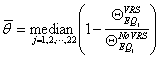
Introduction
Research
Application
Teaching
Publications
Download
Issues
Others


Our Lab

Collapse Prevention Committee