Effects of Seismic and Progressive Collapse Designs on the Vulnerability of RC Frame Structures

Kaiqi Lin [1] , Yi Li [2] , Xinzheng Lu [3] , Hong Guan [4]

Journal of Performance of Constructed Facilities-ASCE,
Accepted on Apr. 30, 2016, DOI: 10.1061/(ASCE)CF.1943-5509.0000942.

Download Full Text

Abstract: Buildings are exposed to multiple natural hazards over their service lives. Multi-hazard analysis and design of building structures has become a research hotspot worldwide. For these structures, earthquake and progressive collapse are two of the most commonly encountered hazards. However, little research has been conducted to examine the effects of the seismic and progressive collapse designs on the resistance of buildings against multiple hazards. In this study, a series of six-story reinforced concrete (RC) frames are considered and their seismic and progressive collapse designs are performed independently according to the corresponding design codes. Fragility curves are used to assess the seismic and progressive collapse resistance. The interactions between the two designs are discussed by analyzing the fragility curves and the collapse modes. Results show that the progressive collapse design of the RC frame may lead to an undesirable failure mode (i.e., ¡°strong-beam-weak-column¡±) under earthquakes, which indicates that a seismic redesign is necessary subsequent to the progressive collapse design. Note that sequential use of different design codes for a structure may result in material waste yet a sub-optimal structural performance. Therefore, a design method by individually considering different hazards is unsuitable for the multi-hazard prevention and mitigation of building structures. A comprehensive and integrated design method for multi-hazards is thus in great need. The outcome of this study will lay a foundation for future multi-hazard analysis and design of building structures.

Key words: Multi-hazard; fragility curve; seismic design; progressive collapse design; RC frame structure

DOI: 10.1061/(ASCE)CF.1943-5509.0000942

If you need the PDF version of this paper, please email to luxinzheng@sina.com

Introduction

Building structures are exposed to multiple hazards during their service lives, such as earthquake, typhoon, fire, explosion, impact etc. In some cases, different hazards may occur simultaneously or immediately one after another (Ellingwood 2006, Krausmann et al. 2010). Structural safety under multi-hazard environment has already drawn great attention worldwide. Nonetheless, previous research studies mainly focus on the structural performance for an individual hazard (Agarwal and Varma 2014, Li et al. 2014, Lu et al. 2012, Yap and Li 2011). Accordingly, most of the existing design methods for disaster prevention and mitigation are also aimed at individual hazards. With rapid societal and technological development, conventional single-hazard oriented design methods are no longer viable for future advancement of civil engineering practice. It is therefore of great importance to perform a multi-hazard analysis of building structures and propose a comprehensive multi-hazard oriented design method (NSF 2014).

Published literature indicates that the effects of multiple hazards to buildings have been considered to some extent. Quiel and Marjanisvili (2011) evaluated the fire resistance of a damaged steel frame designed to resist progressive collapse according to the latest guidelines of the US Department of Defense (DoD). In their study, the relationship between the remaining passive fire protection and the fire-induced collapse time was discussed. Kamath et al. (2015) performed a set of full-scale loading tests on an earthquake damaged reinforced concrete frame subsequently exposed to fire, through which the residual capacity of the frame subjected to a post-earthquake fire was assessed. Formisano et al. (2015) conducted a robustness assessment for two steel framed buildings, which were respectively designed according to the old and new Italian seismic codes, under seismic loads and column removal scenarios. Jaimes et al. (2015) proposed an evaluation criterion to estimate the losses of a structure exposed to several hazards. Two middle-class houses were taken as examples to illustrate their multi-hazard assessment method. The damage rates for the two houses caused by different hazard sources including earthquakes and hurricanes were calculated. Li and Sasani (2015) and Livingston et al. (2015) evaluated the effects of seismic design and structural integrity requirement on the progressive collapse resistance of RC frames, where the effects of span length, ductility capacity and strength were also discussed. Li et al. (2011a) reviewed the state-of-the-art research progress of multi-hazard analyses from the perspective of design and evaluation, and emphasized the importance of life cycle design and the merit of multi-hazard oriented design. Most of the above-mentioned studies focused either on the response simulation or the damage/economic loss evaluation of structures under multi-hazard environment. However, to improve the structural resistance against multiple hazards, more attention must be paid to an integrated design philosophy for building structures.

A reliable multi-hazard oriented design is the key to improve the disaster prevention and mitigation capacity of buildings. Many years of research efforts have resulted in well-developed single-hazard oriented design methodologies internationally, such as the seismic design codes, fire design codes and progressive collapse design codes. This allows the design of structures in resisting a single hazard to be performed according to the relevant codes, whereby practical requirements can be met. When multiple hazards are considered in a structural design, the current engineering practice is to design the structure using different codes for individual hazards. Subsequently, the individual design outcomes for different hazards are combined to yield the final design. Li et al. (2011a) indicated that reducing the risk of an individual hazard may either reduce or increase the structural vulnerability to other hazards. While qualitative explanations were provided in their study, quantitative analyses, which are more important for engineering practices, were absent. As a matter of fact, although current design codes can meet the requirement of reducing the risk of an individual hazard, the correlation between different design codes is still unknown and little research work has been done on this topic. Consequently, when different design codes are used one after another to deal with individual hazards, it is very likely to generate an over-designed structure with redundant use of construction materials; an even worse by-product could be a conflict of design outcomes derived from different design codes, which may eventually weaken the overall performance of the structure. Therefore, in order to reduce the multi-hazard risks of building structures, a systematic assessment of the current design codes is highly desirable to quantitatively evaluate the interrelationships and interactions amongst these codes, and ultimately lead to a multi-hazard oriented design method.

In regards to the effects of a single-hazard oriented design on the structural resistance against other subsequent hazards, Li and Sasani (2015) and Livingston et al. (2015) compared the progressive collapse resistance of ordinary and special RC frames designed following ACI 318-11 (2011) and ASCE 7 (2010). Their studies revealed that while better ductility resulted from the seismic design, this design led to a weaker performance under the scenario of a column loss. Similar conclusions were also made by Formisano et al. (2015), who discovered that the progressive collapse resistance of a steel frame designed according to the old Italian seismic codes is better than that designed using the new one. However, these existing studies only considered the effects of seismic design on the structural progressive collapse resistance, whereas the interactions between the two designs for both hazards have not been discussed. In addition, the evaluations of the progressive collapse resistance were only performed on the component level in the three studies.

RC frames are one of the most widely used structural systems, having a flexible space arrangement and an efficient material usage. For this reason, RC frames are selected as the focus of this study. Due to large self-weight and proven fire-resistance of concrete, RC frames exhibit superior wind and fire resistances (Li et al. 2015). However, the seismic resistance (Lu et al. 2012) and progressive collapse resistance (Sozen et al. 1998) of RC frames are relatively weaker and special designs are thus required. Two six-story RC frames, being identical in spatial arrangement and plan layout but with different seismic design intensities, are studied herein. Based on the evaluation of the progressive collapse resistances of the two frames, the one under a lower seismic design intensity is redesigned according to the progressive collapse design code, due to its collapse resistance not meeting the code requirement. Subsequently, the fragility curves are established to assess the structural performances of both the original and redesigned frames under earthquake and column removal scenarios. The interactions between the seismic design and progressive collapse design are discussed. The analysis results show that the progressive collapse design has some influence on the seismic resistance of the RC frame. This suggests that the seismic resistance is necessary to be reassessed after performing the progressive collapse design. Then the seismic redesign is conducted after the reassessment. Finally, the structural performance and steel consumption of all these RC frames are compared. This study reveals that a sequential use of different structural design codes for individual hazards would very likely result in a waste of construction materials and a reduction of the global resistance against multiple hazards. The current design method which considers different hazards individually is thus not applicable to multi-hazard prevention and mitigation. To this end, the present study provides a scientific basis for vulnerability analyses and integrated hazard design of structures in a multi-hazard environment.

Study cases

Structural parameters

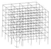
Two structurally identical six-story RC frames are considered in this study and their elevation and plan view are shown in Figure 1. For both, the first story is 4.2 m in height, and the remaining stories are 3.6 m in height. Their first story columns are fully fixed to the ground. Note that such a boundary condition is a commonly used idealization (Fascetti et al. 2015, Lu et al. 2013a, Ren et al. 2015, Tsai and Lin 2008). The dead load on each story is 5.0 kN/m2, whereas the live load on each story is 2.0 kN/m2. The structures are designed following the Chinese design codes [i.e., the code for design of concrete structures (MOHURD 2010a) and the code for seismic design of buildings (MOHURD 2010b)]


Fig. 1. Layout of the six-story RC frame

(a)     Plan view

(b)     Elevation view

Fig. 1. Layout of the six-story RC frame (unit: m)

Seismic design of the RC frames

Two study cases are derived following the two different seismic design levels, designated as RC6 and RC8. RC6 and RC8 have the seismic design intensities of VI and VIII, respectively. Their corresponding design peak ground accelerations (PGA) with a 10% probability of exceedance in 50 years equal to 0.05g and 0.20g, respectively, in which g is the acceleration of gravity. The structural and material parameters (gravity load, material strength, dimension of beams) of RC6 and RC8, as summarized in Table 1, are kept identical as far as possible. Note that due to different requirements of the maximum axial force ratios (i.e., the ratio between the design axial force and the design axial resistance of the columns) specified in the Chinese seismic design code (MOHURD 2010b), the column dimension in RC8 is larger than that in RC6. Specifically, the maximum axial force ratio for the design intensity of VI is 0.9, while that for the design intensity of VIII is 0.75. Note that different column sizes also result in different self-weights in RC6 and RC8 (Table 1). The basic dynamic properties of the two frames are also given in Table 1. The reinforcement arrangement and reinforcement ratio of the typical beams and columns in Zone A (Figure 1) are given in Figure 2.

Table 1. Building information of RC6 and RC8

RC6

RC8

Sections

Beam

250mm¡Á500mm

250mm¡Á500mm

Column

400mm¡Á400mm

550mm¡Á550mm

Material consumption

Concrete (m3)a

746.5

835.7

Steel (ton)b

66.3

95.9

Vibration periods (s)

T1 (1st-order translation in X direction)

1.48

1.05

T2 (1st-order translation in Y direction)

1.48

1.05

T3 (1st-order torsion)

1.24

0.88

Self-weight (ton)

2746

2955

Note: aConcrete: C30 (fc = 28.4 MPa); bReinforcing steel: HRB335 (fy = 300 MPa).

Fig. 2. Reinforcement details at Zone A on axis C of the RC frames

Note: ar: Reinforcement ratio.

Fig. 2. Reinforcement details at Zone A on axis C of the RC frames (unit: mm)

Numerical model and validation

Finite element (FE) simulation has been proven to be the most widely used methodology for hazard analyses of building structures (Ren et al. 2015, Xie et al. 2015, Xu et al. 2012). Published literature (Li et al. 2011b, Lu et al. 2012, Lu et al. 2013a, Miao et al. 2011, Ren et al. 2015) has proven that the fiber beam element model, developed by Lu et al. (2013a), is capable of accurately simulating the earthquake induced collapse and progressive collapse of RC frames. For this reason, FE models of the two RC frames were also developed using the fiber element model in this study. It is necessary to note that brittle shear failure is considered in the proposed fiber-beam model. In other words, when the internal shear force exceeds the prescribed shear strength of the fiber-beam element, the strength and the stiffness of the element abruptly drop to zero. However, due to the ¡°strong-shear-weak-bending¡± design principles in the Chinese design code (MOHURD 2010b), the behavior of the structural components in this study are dominated by flexural behavior and no shear failure occurs. To further validate the reliability and accuracy of the fiber beam element model in the progressive collapse simulation of RC frames, a series of column removal experiments of substructures of RC6 were performed (Ren et al. 2014). In these experimental tests, an edge column and an interior column on the ground story (Figure 1) were removed. A 1/3-scaled ratio was adopted in the tests due to the space limitation of the laboratory. Similar scale ratios were also adopted in the work of Yi et al. (2008), Qian and Li (2012a, 2012b, 2012c), which have shown to have little impact on the experimental results. The original dimension of the beams in RC6 is 250 mm ¡Á 500 mm in width ¡Á height and 6 m in span. The cross section of the 1/3-scaled tested beams is 85 mm ¡Á 175 mm and the span is 2 m. The test specimens were completely fixed to the strong boundary beams, which have a much larger section to provide ideal fixities at boundaries. Detailed dimensions of the specimens and the experimental devices are shown in Figure 3, in which the experimental areas of the RC frame are also displayed. The compressive strength of concrete was 37 MPa and the yield strength of reinforcement was 370 MPa. A concentrated load was applied to the beam-column joint until a significant large deformation (i.e., 500 mm) was reached. More details of the experiments can be found in Ren et al. (2014).


Fig. 3. Overview of the test specimens and experimental devices

Fig. 3. Overview of the test specimens and experimental devices

Fig. 3. Overview of the test specimens and experimental devices

Fig. 3. Overview of the test specimens and experimental devices

Fig. 3. Overview of the test specimens and experimental devices

Fig. 3. Overview of the test specimens and experimental devices

(a)      Mid span

(b)       Side span

Fig. 3. Overview of the test specimens and experimental devices (unit: mm)

The tested beams are simulated using the fiber beam element, consisting of 36 concrete fibers and 8 rebar fibers. The numerical simulations of the load-vertical displacement curves are compared to the test results in Figure 4, with good agreement. Note that the second peaks of both curves are induced by the catenary action. The comparison confirms that the fiber beam element model performs fairly well in simulating the behavior of the specimens during progressive collapse, especially the catenary mechanism of the specimens under large deformation. Based on such a validation, this fiber beam element model is used in the subsequent simulations of this study.

Fig. 4. Comparisons between the numerical simulations and the test results

Fig. 4. Comparisons between the numerical simulations and the test results

(a)      Mid span

(b)       Side Span

Fig. 4. Comparisons between the numerical simulations and the test results

Published literature (Tsai and Lin 2008, Yu and Tan 2013, Fragiadakis et al. 2014) indicates that the complicated interaction between the slabs and the beams in resisting earthquake and progressive collapse is still under researched. For this reason, the slab contribution to the seismic and progressive collapse resistances has often been neglected in research which has led to conservative outcomes. In this study, the slab effect is also not considered to simplify the analysis. Instead, the loads on the slab (including its own weight) are assigned to the supporting beams according to the load distribution relationship.

Design methods

Two different hazard-oriented designs of the RC frames are analyzed in this study, i.e., the seismic design and the progressive collapse design.

The seismic designs of the structures are conducted according to the Code for Seismic Design of Buildings (MOHURD 2010b). The structural internal forces under seismic action are calculated by the complete quadratic combination (CQC) method in which the first six vibration modes of the structures are considered. The preliminary design structural internal forces are calculated by combining the structural internal forces under the seismic action, wind load and gravity. Consequently, the final design internal forces are obtained by adjusting the preliminary design structural internal forces, to guarantee the structures exhibit the expected good mechanism to resist seismic action. For example, the deign bending moments of columns are amplified to achieve the ¡°strong-column-weak-beam¡± mechanism.

The progressive collapse design is conducted following the linear static alternate path (AP) method regulated by General Service Administration (GSA) guideline (GSA 2013). Specifically, the linear elastic FE models of the RC frames are established firstly. Then the columns of the RC frames are removed one after another and the structural internal forces are calculated in which the dynamic amplification factor regulated in the GSA guideline is also considered (GSA 2013). Finally, the reinforcement in the structural members will be redesigned using calculated internal forces.

The main differences between these two design methods are: for the progressive collapse design, frame beams are significantly enhanced to resist the vertical collapse load which mainly increases the reinforcement in beams; for the seismic design, beams and columns are both strengthened in which the increased capacities of columns are relatively larger due to the ¡°strong-column-weak-beam¡± requirement.

Evaluation methods

To discuss the interrelationships and interactions between different design codes, it is necessary to assess the structural performance under different hazards. Existing literature has documented researches on both the seismic and progressive collapse performance assessments of building structures (Fascetti et al. 2015, Formisano et al. 2015). The most commonly used approach to describe the structural performance under different hazards with different intensities is the vulnerability analysis method (Vamvatsikos and Cornell 2002).

In this study, the widely accepted incremental dynamic analysis (IDA) method for earthquake engineering research is used to evaluate the structural seismic performance (Lu et al. 2012, Vamvatsikos and Cornell 2002). The fragility curve of a structure under different intensity ground motions can be obtained through IDA, and the collapse probability (i.e., the ratio of the number of ground motions leading to structural collapse to the total number of ground motions) is chosen as the vulnerability index. The RC frames concerned have a regular configuration and a total height of 22.2 m, whose seismic responses are dominated by the first vibration mode. Therefore, Sa(T1) (i.e., the spectral acceleration at the fundamental period T1) is chosen as the ground motion intensity measure according to Lu et al. (2013b), Lu et al. (2013c) and Ye et al. (2013). Twenty-three seismic ground motions are adopted for the vulnerability analysis based on Lu et al.¡¯s work (2012). Of which, 22 ground motions are selected from the far-field record set proposed in the FEMA P695 (2009) and the remaining one is the widely used El-Centro 1940 record (Chopra 2001). The classical Rayleigh damping with a damping ratio of 5% is also adopted.

Unlike seismic performance evaluation, a widely accepted vulnerability evaluation method for progressive collapse is still lacking. An evaluation method similar to the IDA method is adopted in this study to calculate the fragility curve of a progressive collapse. In this method, it is assumed that every typical column in a structure has the same probability to fail. The progressive collapse response is calculated using the nonlinear dynamic AP method. The collapse probability (i.e. Pcollapse) is defined as Equation (1):

Pcollapse = ncollapse/ ntotal                               (1)

in which ncollapse is the number of cases that collapse occurs under a certain gravity load level, and ntotal is the total number of the column removal scenarios. Given random variations of the gravity load on the structure, different gravity load levels are then applied to the structure (i.e., nominal gravity load) during the analyses. Subsequently, the collapse probability (i.e., Pcollapse) of the structure under different nominal gravity loads can be calculated. Finally, the relationship between the collapse probability and the magnitude of the nominal gravity load can be obtained. In other words, a progressive collapse (due to column removal) fragility curve similar to the seismic fragility curve can be derived.

Detailed implementation to calculate the progressive collapse fragility curve is as follows: (a) According to the progressive collapse design guidelines (CECS 2014, DoD 2010, GSA 2013), every column on each story of the structure is removed in turn, after the structure reaches the static equilibrium under gravity load. (b) The responses of the structure after individual column removal are calculated through nonlinear dynamic analysis. A vertical displacement of 1/5 span of the beam is considered as the structural failure criterion (DoD 2010). (c) The gravity load on the structure is changed from zero to infinity to generate the progressive collapse fragility curve subjected to different nominal gravity loads.

Evaluation results of RC6 and RC8

Based on the vulnerability analysis method outlined above, the seismic performance and progressive collapse resistance of the two RC frames, RC6 and RC8, are evaluated, using the seismic and the progressive collapse fragility curves.

Evaluation of seismic performance

The seismic fragility curves of RC6 and RC8 are shown in Figure 5(a), in which the x-axis is the ground motion intensity Sa(T1) and the y-axis is the collapse probability. Note that the curves for RD6-RD and RD6-RD2 will be discussed in the Sections ¡°Progressive collapse design of RC6¡± and ¡°Redesign of RC6-RD for earthquake¡±. Note also that a lognormal distribution curve is used to fit the collapse fragility analysis results. Here, Sa(T1) corresponds to 50 % collapse probability is defined as Sa(T1)50%. It is evident from the figure that Sa(T1)50% for RC6 is 0.42 g while Sa(T1)50% for RC8 equals 1.38 g. This is because Sa(T1)MCE (i.e., Sa(T1) for the maximum considered earthquake (MCE)) for RC8 is 0.34 g (MOHURD 2010b), which is four times larger than that for RC6 (i.e., 0.08 g) (MOHURD 2010b). As a result, the seismic resistance of RC8 is much greater than that of RC6.

Fig. 5. Fragility curves of the RC frames

Fig. 5. Fragility curves of the RC frames

(a)      Seismic fragility curves of the RC frames

(b)     Progressive collapse fragility curves of the RC frames

Fig. 5. Fragility curves of the RC frames

Evaluation of progressive collapse resistance

The progressive collapse fragility curves of the two frames are displayed in Figure 5(b) using the evaluation method outlined in the Section ¡°Evaluation methods¡±. Again the curves for RD6-RD and RD6-RD2 will be discussed in the Sections ¡°Progressive collapse design of RC6¡± and ¡°Redesign of RC6-RD for earthquake¡±. Note that when taking the slabs into consideration, beams will be strengthened and the progressive collapse resistance will be increased according to Ren et al. (2014).

Figure 5(b) indicates that the progressive collapse resistance of RC8 is significantly larger than that of RC6. The collapse probability of RC6 and RC8 are 83.3 % and 0 %, respectively, under the design gravity load (i.e., the nominal gravity equals 1.0 g). Thus, RC8 meets the requirement of DoD 2010, GSA 2013 and Chinese code (CECS 2014) under the design gravity load whereas RC6 does not. In addition, the progressive collapse of RC6 is triggered by removing one of the columns on the first to the fifth story. The collapse modes of RC6 when one of the typical columns on the first story is removed are shown in Figure 6. In contrast, RC8 does not collapse at all under the design gravity load, regardless of any column removal.

Fig. 6. Collapse modes of RC6 in different column removal scenarios (Nominal gravity = 1.0g)

Fig. 6. Collapse modes of RC6 in different column removal scenarios (Nominal gravity = 1.0g)

Fig. 6. Collapse modes of RC6 in different column removal scenarios (Nominal gravity = 1.0g)

(a)      Corner column

(b)     Edge column

(c)      Interior column

Fig. 6. Collapse modes of RC6 in different column removal scenarios (Nominal gravity = 1.0g)

The results further suggest that a higher seismic design intensity, as for RC8, can effectively improve the progressive collapse resistance. RC6, on the other hand, cannot meet the requirement of progressive collapse design codes (CECS 2014, DoD 2010, GSA 2013) and an additional progressive collapse design is thus necessary.

Progressive collapse design of RC6

Design procedure

RC6 is redesigned following the linear static AP method as specified in the Section ¡°Design methods¡±. The redesigned RC6 following the progressive collapse design procedure is named as RC6-RD.

Evaluation of the performance of RC6-RD

As the amount of reinforcement of RC6-RD changes significantly as compared to RC6, the seismic performance and progressive collapse resistance of RC6-RD will be re-evaluated.

Evaluation of progressive collapse resistance

The progressive collapse fragility curve of RC6-RD is presented in Figure 5(b). As evident, the progressive collapse resistance of RC6-RD is significantly improved compared to RC6. Further, the collapse probability is reduced to no space under the design gravity load, thereby meeting the requirement of the progressive collapse design codes (CECS 2014, DoD 2010, GSA 2013).

Comparison of steel consumption

Note that the progressive collapse design procedure described in the Section ¡°Progressive collapse design of RC6¡± does not affect the reinforcement amount in the columns. The additional reinforcement due to progressive collapse design is located in the beams only. A comparison of the amount of longitudinal reinforcement in the beams of RC6, RC6-RD and RC8 is given in Table 2.

Table 2 indicates that the amount of longitudinal reinforcement in the beams of RC6 is much less than that of RC8 due to the lower seismic design intensity for RC6. Subsequent to the progressive collapse design, the reinforcement amount in the beams of RC6-RD increases significantly compared to that in RC6. On the first to third stories of the building, the reinforcement amount in the beams of RC6-RD is less than that in RC8. However, for the fourth to fifth stories, RC6-RD has slightly more reinforcement in the beams than RC8. Overall, the total amount of longitudinal reinforcement in RC6-RD is slightly less than that in RC8.

Table 2. Comparison of the amount of longitudinal reinforcement in beams

Story

RC6

RC6-RD

RC8

Reinforcement (ton)

Reinforcement (ton)

Percentage increase (%)a

Reinforcement (ton)

Percentage increase (%)a

1st

2.20

4.04

83.9

4.67

112.8

2nd

2.09

3.90

86.7

4.66

122.7

3rd

1.97

3.66

86.0

4.09

108.1

4th

1.92

3.59

87.4

3.31

73.0

5th

1.88

3.59

94.3

2.43

29.2

6th

1.85

1.85

0

1.98

7.1

Total

11.89

20.70

73.9

21.14

77.7

Note: aCompared to the reinforcement amount of RC6.

Evaluation of seismic performance

In the existing studies, design for an individual hazard only evaluates the effect of such a design on the targeted hazard. However, the effects of such a design on other subsequent hazards are often neglected. According to Li et al. (2011a), improving the structural resistance against an individual hazard may affect the structural vulnerability to other hazards either positively or negatively. Following the progressive collapse design, the reinforcement amount in RC6-RD becomes quite different from that in RC6, which may affect the seismic performance of the building. Therefore, a re-evaluation of the seismic performance of RC6-RD from both the component and structural levels is desirable.

(1) Component level

For RC6, RC6-RD and RC8, the nominal flexural strengths at the end of the selected beams (i.e. Mb) on each story are given in Table 3, in which Mb is defined following Specification 18.7.3.2 of ACI 318 (ACI 2014). On the first to third stories, the order of Mb is RC8 > RC6-RD > RC6. It changes to RC6-RD > RC8 > RC6 on the fourth and fifth stories. This relationship is similar to the distribution of the longitudinal reinforcement in frame beams along the height. This is because RC8, with a higher seismic design intensity, has a 4-time larger design seismic force than RC6, the reinforcement amount in RC8 is therefore mainly determined by the seismic load. In contrast, the reinforcement amount in RC6 is mainly controlled by the gravity load. As a result, the Mb values of RC8 are significantly larger than those of RC6. In addition, following the progressive collapse design, the Mb values of RC6-RD are greatly increased and close to those of the corresponding beams of RC8.

Table 3. Comparison of the nominal flexural strengths Mb at the end of the RC frame beams (unit: kN¡¤m)

Story

Location

RC6

RC8

RC6-RD

1st

C

89

255

189.6

M

126

308

301.6

2nd

C

80

250

184.8

M

121

312

294.4

3rd

C

73

221

181.6

M

114

282

288.8

4th

C

66

183

180

M

110

241

284.8

5th

C

60

136

184.8

M

106

191

290.4

6th

C

62

93

62

M

108

103

108

Note: C-Corner beam; M-Middle beam.

Note that, with an increase of nominal flexural strengths at the end of the beams (i.e. Mb), the strength ratio between the nominal flexural strengths of the beams (i.e. Mb) and those of the adjoining columns (i.e. Mc) changes as well. Note also that, according to the capacity design principle, the columns are expected to be much stronger than the beams during earthquakes. Thus, a ¡°strong-column-weak-beam¡± requirement is specified in many international seismic design codes (MOHURD 2010b, ACI 2014), as expressed by the following equation:

¡ÆMc ¡Ý hc¡ÆMb                              (2)

in which ¡ÆMc is the sum of the nominal flexural strengths of the columns framing into the joint, ¡ÆMb is the sum of the nominal flexural strengths of the conjoining beams, hc is the ¡°strong-column-weak-beam¡± ratio. For the six-story RC frames studied herein, hc is set as 1.2 according to the Chinese seismic design code (MOHURD 2010b). Note that this ratio is the same for ACI 318-14 (ACI 2014).

The column-to-beam strength ratios at the middle joints of the RC frames (i.e., SMc / SMb) are given in Table 4. Note that for the joints on the roof of the RC frames, a ratio smaller than hc (i.e., 1.2) is permitted in the Chinese seismic design code (MOHURD 2010b). The progressive collapse design results in a significant increase in the flexural strengths of the beams in RC6, which may violate the requirement of Equation 2. As a result, the columns in RC6-RD are relatively weaker and may fail in earthquakes prior to the beams. Note that when taking slab into consideration, the ¡°strong-beam-weak-column¡± failure will also be more severe after the progressive collapse design (Lu et al. 2012). To further illustrate this phenomenon, the seismic performance of RC6-RD is re-evaluated from the structural level as presented below.

Table 4. The column-to-beam strength ratios at the middle joints of the RC frames (i.e., ¡ÆMc / ¡ÆMb)

Story

RC6

RC8

RC6-RD

RC6-RD2

1st

1.25

1.92

0.52

1.20

2nd

2.10

1.51

0.86

1.20

3rd

2.37

1.53

0.93

1.20

4th

2.28

1.57

0.88

1.20

5th

2.05

1.41

0.75

1.20

6th

0.93

1.06

0.93

0.93

(2)    Structural level

Similarly, the IDA of RC6-RD is performed and the result is presented in Figure 5(a). Although the amount of longitudinal reinforcement in the beams of RC6-RD is 73.9% greater than that of RC6, its seismic performance does not increase noticeably compared to that of RC6, which indicates that the progressive collapse design has limited effects on the structural seismic performance. The collapse PGAs of RC6 and RC6-RD under the 23 ground motions are illustrated in Figure 7.

Fig. 7. The seismic collapse PGA of RC6 and RC6-RD

Fig. 7. The seismic collapse PGA of RC6 and RC6-RD

In general, the seismic performance of RC6-RD is close to that of RC6. Sometimes, the seismic performance of RC6-RD is even worse than that of RC6. Among the 23 ground motions, for 9 ground motions, the collapse PGA of RC6-RD is larger than that of RC6; for 7 ground motions, the collapse PGA of RC6-RD approximately equals that of RC6; for the other 7 ground motions, the collapse PGA of RC6-RD is even smaller than that of RC6. Therefore, the progressive collapse design affects the structural seismic resistance. The newly added reinforcement in RC6-RD may result in the ¡°strong-beam-weak-column¡± failure mode and weaken the structural seismic resistance, which will be further illustrated in the next section. Consequently, a seismic redesign after the progressive collapse design is necessary to ensure the nominal flexural strengths of the beams and columns meet the requirement of Equation 2.

Redesign of RC6-RD for earthquake

Design procedure

In order to prevent the ¡°strong-beam-weak-column¡± failure mode from occurring after the progressive collapse design, the nominal flexural strength of the columns of RC6-RD is increased according to Equation 2 by adding reinforcement in the columns (MOHURD 2010b, ACI 2014). The new frame with column strengthening is named as RC6-RD2.

Evaluation of the performance of RC6-RD2

Similarly, the structural performance of RC-RD2 is also evaluated from the perspectives of progressive collapse resistance, material consumption and seismic resistance.

Evaluation of the progressive collapse resistance

The progressive collapse fragility curve of RC6-RD2 is given in Figure 5(b), which is shown to overlap that of RC6-RD. This is because only the column reinforcement is increased in the process of seismic redesign, while the reinforcement in the beams remains the same as RC6-RD. Note that the progressive collapse resistance of the RC frame mainly relies on the reinforcement in the beams. Consequently, the progressive collapse resistance of RC6-RD2 is essentially the same as that of RC6-RD.

Comparison of steel consumption

A comparison of the amount of longitudinal reinforcement in the columns of RC6, RC6-RD, RC6-RD2 and RC8 is shown in Table 5. After the seismic redesign, the reinforcement amount in the columns of RC6-RD2 is 3.8 times larger than that of RC6 and RC6-RD, which means that more reinforcement should be added to ensure that Equation 2 is satisfied.

Table 5. Comparison of the amount of longitudinal reinforcement in columns

Story

RC6 & RC6-RD

RC6-RD2

RC8

Reinforcement (ton)

Reinforcement (ton)

Percentage increase (%)a

Reinforcement (ton)

Percentage increase (%)a

1st

1.28

4.80

274.9

5.95

365.3

2nd

0.79

3.89

394.6

2.01

155.3

3rd

0.79

3.38

329.0

2.01

155.3

4th

0.79

3.01

282.2

2.01

155.3

5th

0.79

3.87

391.2

2.01

155.3

6th

0.79

0.79

0

2.01

155.3

Total

5.22

19.73

278.3

16.01

206.8

Note: aCompared to the reinforcement amount of RC6.

Evaluation of the seismic performance

The seismic fragility curve of RC6-RD2 is shown in Figure 5(a). Following the seismic redesign, the seismic performance of RC6-RD is improved significantly yet still weaker than RC8.

Subjected to the same FRIULI-TMZ000 ground motion, Figure 8 shows the plastic hinge distribution of RC6-RD and RC6-RD2 at collapse. The seismic redesign can significantly improve the failure mode of RC6 in earthquake. The plastic hinges of RC6-RD on the third to the top stories are mainly located at both ends of the columns and only a limited number of plastic hinges at the beam ends are observed from Axis 2 to Axis 4. Large displacements occurred on the first and second stories which lead to the collapse of the entire structure. In contrast, the plastic hinge distribution of RC6-RD2 is more uniform and rational. Many plastic hinges appear in the beams of RC6-RD2, which dissipate more energy and significantly improve the seismic performance. The collapse PGA of RC-RD2 is 1.8 g larger than that of RC6-RD under FRIULI-TMZ000 ground motion. Conclusively, the seismic redesign can greatly improve the seismic resistance of RC frames after performing the progressive collapse design.

Fig. 8. The plastic hinge distribution of RC6-RD and RC6-RD2 (Ground motion input: FRIULI-TMZ000)

(a)      RC6-RD (PGA = 2.3 g)

(b)     RC6-RD2 (PGA = 4.1 g)

Fig. 8. The plastic hinge distribution of RC6-RD and RC6-RD2 (Ground motion input: FRIULI-TMZ000)

Comparison of the total longitudinal reinforcement consumption

The total longitudinal reinforcement consumptions of the four RC frames are listed in Table 6, with a descending order of RC6-RD2 > RC8 > RC6-RD > RC6. RC6-RD2, which is generated by the progressive collapse design and the seismic redesign of RC6, has the largest steel consumption. Yet its seismic performance is still weaker than RC8. This implies that more material consumption in RC6-RD2 does not necessarily result in a better structural performance. Conclusively, if different single-hazard oriented codes are used individually to cover multiple hazard considerations, it is very likely to produce an over-designed structure with material waste yet the structural performance may not be the optimum. A multi-hazard oriented design method is thus needed.

Table 6. Total longitudinal reinforcement consumptions of the four RC frames

RC6

RC6-RD

RC6-RD2

RC8

Steel consumption (ton)

17.11

25.91

40.42

38.14

Conclusion

The structural safety under a multi-hazard environment has already drawn great attention worldwide. A comprehensive design method catering for the complicated multi-hazard environment is becoming a future trend of civil engineering research. A series of RC frames are studied in this study. The progressive collapse and the seismic designs of the frames are performed and the fiber beam element models of these frames are established to assess their performances. Two progressive collapse experiments are simulated to validate the feasibility and reliability of the fiber beam element models. Based on the validation, the vulnerability analysis method is used in this study to evaluate the seismic performance and the progressive collapse resistance of the four RC frames. The main conclusions are as follows:

(1)    Interactions do exist among different design codes. When the seismic design intensity of an RC frame increases from VI to VIII degree, its progressive collapse resistance will be increased as well. However, the progressive collapse design has limited effects on the structural seismic performance. Meanwhile, the progressive collapse design may result in the ¡°strong-beam-weak-column¡± failure mode and weaken the structural seismic resistance. A seismic reassessment and redesign is necessary after performing the progressive collapse design.

(2)    Sequential use of different design codes in a structure may lead to material waste yet a sub-optimal performance. The RC6-RD2, which is generated by the progressive collapse design and seismic redesign of RC6, has a larger amount of longitudinal reinforcement. Yet it is still weaker than RC8 in earthquakes. The current single-hazard oriented design method is not suitable for the multi-hazard prevention and mitigation of building structures.

(3)    To achieve a resilient design of building structures in the multi-hazard environment, it is of great importance to consider all the possible hazards in the service life of building structures and propose a comprehensive and integrated multi-hazard oriented design method.

Acknowledgment

The authors are grateful for the financial support received from the National Basic Research Program of China (973 Program) (No. 2012CB719703), the National Natural Science Foundation of China (No. 51578018) and Australian Research Council through an ARC Discovery Project (DP150100606).

References

American Concrete Institute (ACI). (2011). ¡°Building code requirements for structural concrete (ACI 318-11) and commentary (318R-11).¡± Detroit, MI.

American Concrete Institute (ACI). (2014). ¡°Building code requirements for structural concrete (ACI 318-14) and commentary (318R-14).¡± Detroit, MI.

Agarwal, A., and Varma, A. H. (2014). ¡°Fire induced progressive collapse of steel building structures: The role of interior gravity columns.¡± Eng. Struct., 58, 129-140.

ASCE/Structural Engineering Institute (SEI). (2010). ¡°Minimum design loads for buildings and other structures.¡± SEI 7, Reston, VA.

China Association for Engineering Construction Standardization (CECS). (2014). ¡°Code for anti-collapse design of building structures.¡± CECS 392: 2014, Beijing. (in Chinese)

Chopra, A. K. (2001). Dynamics of structures: theory and applications to earthquake engineering. Second Edition, Prentice Hall, Upper Saddle River, NJ, 245-249.

Department of Defense (DoD). (2010). ¡°Design of structures to resist progressive collapse.¡± Unified facility criteria, UFC 4-023-03, Washington, DC.

Ellingwood, B. R. (2006). ¡°Mitigating risk from abnormal loads and progressive collapse.¡± J. Perform. Constr. Facil., 10.1061/(ASCE)0887-3828(2006)20:4(315), 315-323.

Fragiadakis, M., Vamvatsikos, D., and Aschheim, M. (2014). ¡°Application of nonlinear static procedures for the seismic assessment of regular RC moment frame buildings.¡± Earthq. Spectra, 30(2), 767-794.

Fascetti, A., Kunnath, S. K., and Nistic¨°, N. (2015). ¡°Robustness evaluation of RC frame buildings to progressive collapse.¡± Eng. Struct., 86, 242-249.

Federal Emergency Management Agency (FEMA). (2009). ¡°Quantification of building seismic performance factors.¡± FEMA 695, Washington, DC.

Formisano, A., Landolfo, R., and Mazzolani, F. M. (2015). ¡°Robustness assessment approaches for steel framed structures under catastrophic events.¡± Comput. Struct., 147, 216-228.

General Services Administration (GSA). (2013). Alternate path analysis and design guidelines for progressive collapse resistance. Washington, DC.

Jaimes, M. A., Reinoso, E., and Esteva, L. (2015). ¡°Risk analysis for structures exposed to several multi-hazard sources.¡± J. Earthq. Eng., 19(2), 297-312.

Kamath, P., Sharma, U. K., Kumar, V., Bhargava, P., Usmani, A., Singh, B., Singh, Y., Torero, J., Gillie, M., and Pankaj, P. (2015). ¡°Full-scale fire test on an earthquake-damaged reinforced concrete frame.¡± Fire Safety J., 73(3), 1-19.

Krausmann, E., Cruz, A. M., and Affeltranger, B. (2010). ¡°The impact of the 12 May 2008 Wenchuan earthquake on industrial facilities.¡± J. Loss Prevent. Proc., 23(2), 242-248.

Li, M., and Sasani, M. (2015). ¡°Integrity and progressive collapse resistance of RC structures with ordinary and special moment frames.¡± Eng. Struct., 95, 71-79.

Li, Y., Ahuja, A., and Padgett, J. E. (2011a). ¡°Review of methods to assess, design for, and mitigate multiple hazards.¡± J. Perform. Constr. Facil., 10.1061/(ASCE)CF.1943-5509.0000279, 104-117.

Li, Y., Lu, X.Z., Guan, H., and Ye, L.P. (2011b). ¡°An improved tie force method for progressive collapse resistance design of reinforced concrete frame structures¡±, Eng. Struct., 33(10), 2931-2942.

Li, Y., Lu, X. Z., Guan, H., and Ye, L. P. (2014). ¡°Progressive collapse resistance demand of RC frames under catenary mechanism.¡± ACI Struct. J., 111 (5), 1225-1234.

Li, Y., Lu, X. Z., Guan, H., Ying, M. J., and Yan, W. M. (2015). ¡°A case study on a fire-induced collapse accident of a reinforced concrete frame-supported masonry structure.¡± Fire Tech., 10.1007/s10694-015-0491-0.

Livingston, E., Sasani, M., Bazan, M., and Sagiroglu, S. (2015). ¡°Progressive collapse resistance of RC beams.¡± Eng. Struct., 95, 61-70.

Lu, X., Lu, X. Z., Guan, H., and Ye, L. P. (2013a). ¡°Collapse simulation of reinforced concrete high-rise building induced by extreme earthquakes.¡± Earthq. Eng. Struct. Dyn., 42(5), 705-723.

Lu, X., Lu, X. Z., Guan, H., and Ye, L. P. (2013b). ¡°Comparison and selection of ground motion intensity measures for seismic design of super high-rise buildings.¡± Adv. Struct. Eng., 16(7), 1249-1262.

Lu, X., Ye, L. P., Lu, X. Z., Li, M. K., and Ma, X. W. (2013c). ¡°An improved ground motion intensity measure for super high-rise buildings.¡± Sci. China-Technol. Sci., 56(6), 1525-1533.

Lu, X. Z., Ye, L. P., Ma, Y. H., and Tang, D. Y. (2012). ¡°Lessons from the collapse of typical RC frames in Xuankou School during the great Wenchuan Earthquake.¡± Adv. Struct. Eng., 15(1), 139-153.

Miao, Z. W., Ye, L. P., Guan, H., and Lu, X. Z. (2011). ¡°Evaluation of modal and traditional pushover analyses in frame-shear-wall structures.¡± Adv. Struct. Eng., 14(5), 815-836.

Ministry of Housing and Urban-Rural Development of the People¡¯s Republic of China (MOHURD). (2010a). ¡°Code for design of concrete structures.¡± GB50010-2010, Beijing, China.

Ministry of Housing and Urban-Rural Development of the People¡¯s Republic of China (MOHURD). (2010b). ¡°Code for seismic design of buildings.¡± GB50011-2010, Beijing, China.

National Science Foundation (NSF). (2014). ¡°Decision Frameworks for multi-hazard resilient and sustainable buildings (RSB).¡± <http://www.nsf.gov/pubs/2014/nsf14557/nsf14557.htm?WT.m
c_id=USNSF_30&WT.mc_ev=click > (Jul. 20, 2014)

Qian, K., and Li, B. (2012a). ¡°Dynamic performance of RC beam-column substructures under the scenario of the loss of a corner column - Experimental results.¡± Eng. Struct., 42, 154-167.

Qian, K., and Li, B. (2012b). ¡°Performance of three-dimensional reinforced concrete beam-column substructures under loss of a corner column scenario¡±. J. Struct. Eng., 139(4): 584-594.

Qian, K., and Li, B. (2012c). ¡°Slab effects on response of reinforced concrete substructures after loss of corner column.¡± ACI Struct. J., 109(6), 845-856.

Quiel, S. E., and Marjanishvili, S. M. (2011). ¡°Fire resistance of a damaged steel building frame designed to resist progressive collapse.¡± J. Perform. Constr. Facil., 10.1061/(ASCE)CF.1943-5509.0000248, 402-409.

Ren, P. Q., Li, Y., Guan, H., and Lu, X. Z. (2015). ¡°Progressive collapse resistance of two typical high-rise RC frame shear wall structures.¡± J. Perform. Constr. Facil., 10.1061/(ASCE)CF.1943-5509.0000593, 04014087.

Ren, P. Q., Li, Y., Zhou, Y., Lu, X. Z., and Guan, H. (2014). ¡°Experimental study on the progressive collapse resistance of RC slabs.¡± Proc., Structures Congress 2014, Bell, G.R., and Card, M. A. Reston, ed., American Society of Civil Engineers (ASCE), Reston, VA, 868-879.

Sozen, M., Thornton, C., Corley, W., and Sr., P. (1998). ¡°The Oklahoma City Bombing: Structure and Mechanisms of the Murrah Building.¡± J. Perform. Constr. Facil., 10.1061/(ASCE)0887-3828(1998)12:3(120), 120¨C136.

Tsai, M.H., and Lin, B.H. (2008). ¡°Investigation of progressive collapse resistance and inelastic response for an earthquake-resistant RC building subjected to column failure¡±. Eng. Struct., 30(12): 3619-28. doi: 10.1016/j.engstruct.2008.05.031.

Vamvatsikos, D., and Cornell., C. A. (2002) ¡°Incremental dynamic analysis.¡± Earthq. Eng. Struct. Dyn., 31(3), 491-514.

Xie, L. L., Lu, X. Z., Guan, H., and Lu, X. (2015). ¡°Experimental study and numerical model calibration for earthquake-induced collapse of RC frames with emphasis on key columns, joints and the overall structure.¡± J. Earthq. Eng., 10.1080/13632469.2015.1040897.

Xu, Z., Lu, X. Z., Guan, H., Lu, X., and Ren, A. Z. (2012). ¡°Progressive-collapse simulation and critical region identification of a stone arch bridge.¡± J. Perform. Constr. Facil., 10.1061/(ASCE)CF.1943-5509.0000329, 43-52.

Yap, S. L., and Li, B. (2011). ¡°Experimental investigation of reinforced concrete exterior beam-column subassemblages for progressive collapse.¡± ACI Struct. J., 108(5): 542-552.

Ye, L. P., Ma, Q. L., Miao, Z. W., Guan, H., and Zhuge, Y. (2013). ¡°Numerical and comparative study of earthquake intensity indices in seismic analysis.¡± Struct. Des. Tall Spec., 22(4), 362-381.

Yi, W. J., He, Q. F., Xiao, Y., and Kunnath, S. K. (2008). ¡°Experimental study on progressive collapse-resistant behavior of reinforced concrete frame structures.¡± ACI Struct. J., 105(4), 433-439.

Yu, J., and Tan, K. H. (2013). ¡°Experimental and numerical investigation on progressive collapse resistance of reinforced concrete beam column sub-assemblages.¡± Eng. Struct., 55, 90-106. doi: 10.1016/j.engstruct.2011.08.040


[1] PhD Student, Beijing Engineering Research Center of Steel and Concrete Composite Structures, Tsinghua University, Beijing 100084, China.

[2] Associate Professor, Key Laboratory of Urban Security and Disaster Engineering of Ministry of Education, Beijing Univ. of Technology, Beijing 100124, China.

[3] Professor, Key Laboratory of Civil Engineering Safety and Durability of China Education Ministry, Department of Civil Engineering, Tsinghua University, Beijing 100084, P.R. China (corresponding author). E-mail: luxz@tsinghua.edu.cn

[4] Professor, Griffith School of Engineering, Griffith Univ., Gold Coast Campus, QLD 4222, Australia.

Introduction
Research
Application
Teaching
Publications
Download
Issues
Others


Our Lab

Collapse Prevention Committee